
Door locking apparatus

a door locking and electronic technology, applied in the field of electronic door locking apparatus, can solve the problems of user outside the door never opening, easy damage, and door locking apparatuses using such mortise locks do not satisfactorily play the role, and achieve the effect of easy opening the door

Inactive Publication Date: 2010-10-26
KEICO HIGHTECH
View PDF15 Cites 19 Cited by
  • Summary
  • Abstract
  • Description
  • Claims
  • Application Information

AI Technical Summary

Benefits of technology

[0017]Accordingly, the present invention is designed to solve such drawbacks of the prior art, and therefore an object of the present invention is to provide an electronic door locking apparatus capable of easily opening a door from the outside by inserting a metal card, which has a magnet installed inside, into an emergency release assembly if a power source such as a dry battery is not supplied or when the locking apparatus is not useable due to other mechanical defects.
[0018]Another object of the present invention is to provide a door locking apparatus capable of performing a lock function since a dead bolt is locked if a door handle of an outer unit is rotated upwards when there are defects in a driving motor or electronic components.
[0019]Still another object of the present invention is to provide a door locking apparatus capable of performing a perfect crime prevention function since the door is automatically opened by means of the card and the fingerprint and locked when the door is closed, but the door may be manually locked by turning a hand grip upwards in the worst case where there are defects in the electronic parts or the mechanical parts.
[0020]Yet another object of the present invention is to provide a door locking apparatus capable of ensuring safety in opening the door by employing a mechanical connection system regardless of automatically opening the door with a barium ferrite emergency card, other than a key, into which magnetic data is inputted, regardless of the components burned or melted in the emergency such as a fire since the door is not opened by the motor but mechanically opened in a one-touch system by an operation of a lever along with the latch bolt and the dead bolt while one is out.
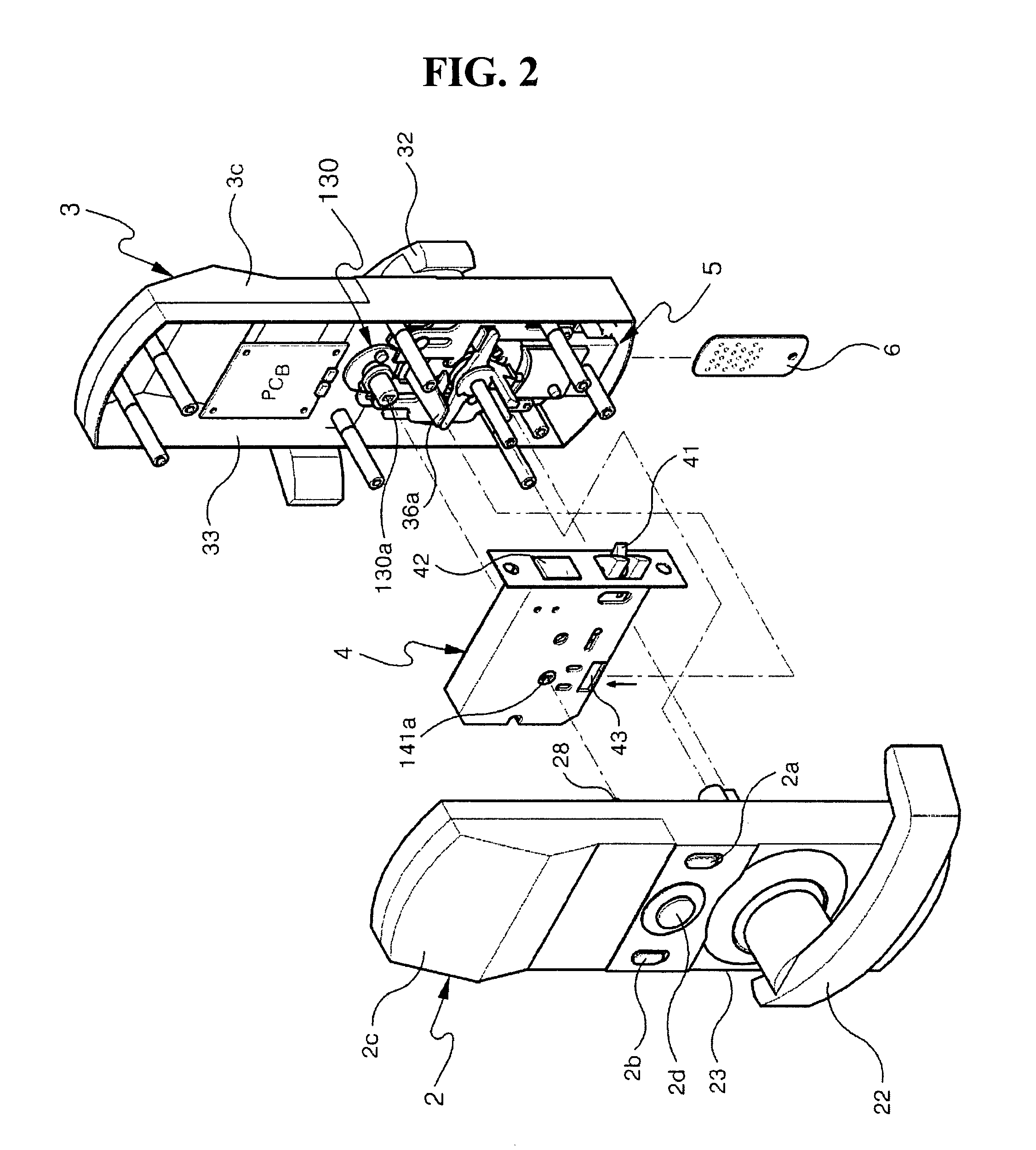
[0030]Meanwhile, the emergency release assembly preferably includes a body including an opening for inserting an emergency card and a reception groove and fixed in the housing of the outer unit; upper / lower plates for easily inserting the emergency card inserted into the opening of the body; an elastic plate for resiliently supporting the upper / lower plates against the body; a magnet-fixed clamp plate installed onto the upper plates and having through holes for receiving a plurality of cylindrical magnets, formed therein; a first slider having a plurality of grooves and a spring reception groove formed therein and being able to be slid by the emergency card, the grooves corresponding to the through holes of the magnet-fixed clamp plate; a plurality of magnets arranged between the magnet-fixed clamp plate and the first slider to permit the first slider to move only when a valid emergency card is inserted since it is operated by means of an impact and a repulsion of the emergency card when inserting the emergency card; a cover fixed in the body to receive the upper / lower plates, the elastic plate, the magnet-fixed clamp plate, the first slider and the magnets into the reception groove of the body, and simultaneously fixed in the housing and having an opening; a second slider fixed in the first slider through the opening of the cover and slid to give a bias force so that the rotary moving body and the plunger are rotated together; and a rod and a spring being able to be inserted into the reception groove to supply a restoring force to the first slider.

Problems solved by technology

However, a variety of the door locking apparatuses using such a mortise lock do not satisfactorily play a role as the locking apparatus or is easily damaged due to its complex configuration and instability in its operation between components if it is used for an extended time.
Accordingly, the electrical components have a problem in that the authorized user outside the door never opens the door without help from a person inside the door when power is not supplied since the electrical components are operated only when they are connected to an internal power source or an external power source.
Also, if a door handle of an outer unit includes a separate cylinder key, a door may be damaged by drilling outside the door when one forcibly opens the door, and therefore it is uneconomical since the entire door locking apparatus may be replaced.
That is to say, conventional electronic door locks are automatically opened using a password, a card and a fingerprint, and automatically locked when the door is closed, but have a problem in that they cannot perform a crime prevention function since it functions as a locking apparatus while one is out because its dead bolt is not locked if a motor or electronic and mechanical parts are out of order.
Also, the door is automatically closed by operation of the motor while one is out, and the dead bolt is not interlocked by the keypad since an emergency, such as a fire, melts the electronic components, and it is therefore difficult to bring the fire under control.

Method used


Image

  • Door locking apparatus
  • Door locking apparatus
  • Door locking apparatus

Examples


Embodiment Construction

[0060]Hereinafter, embodiments according to the present invention will be described with reference to the accompanying drawings. Here, when one element is connected to another element, one element may be not only directly connected to another element but also indirectly connected to another element via another element. Furthermore, irrelevant elements have been omitted for clarity. Also, like reference numerals refer to like elements throughout.

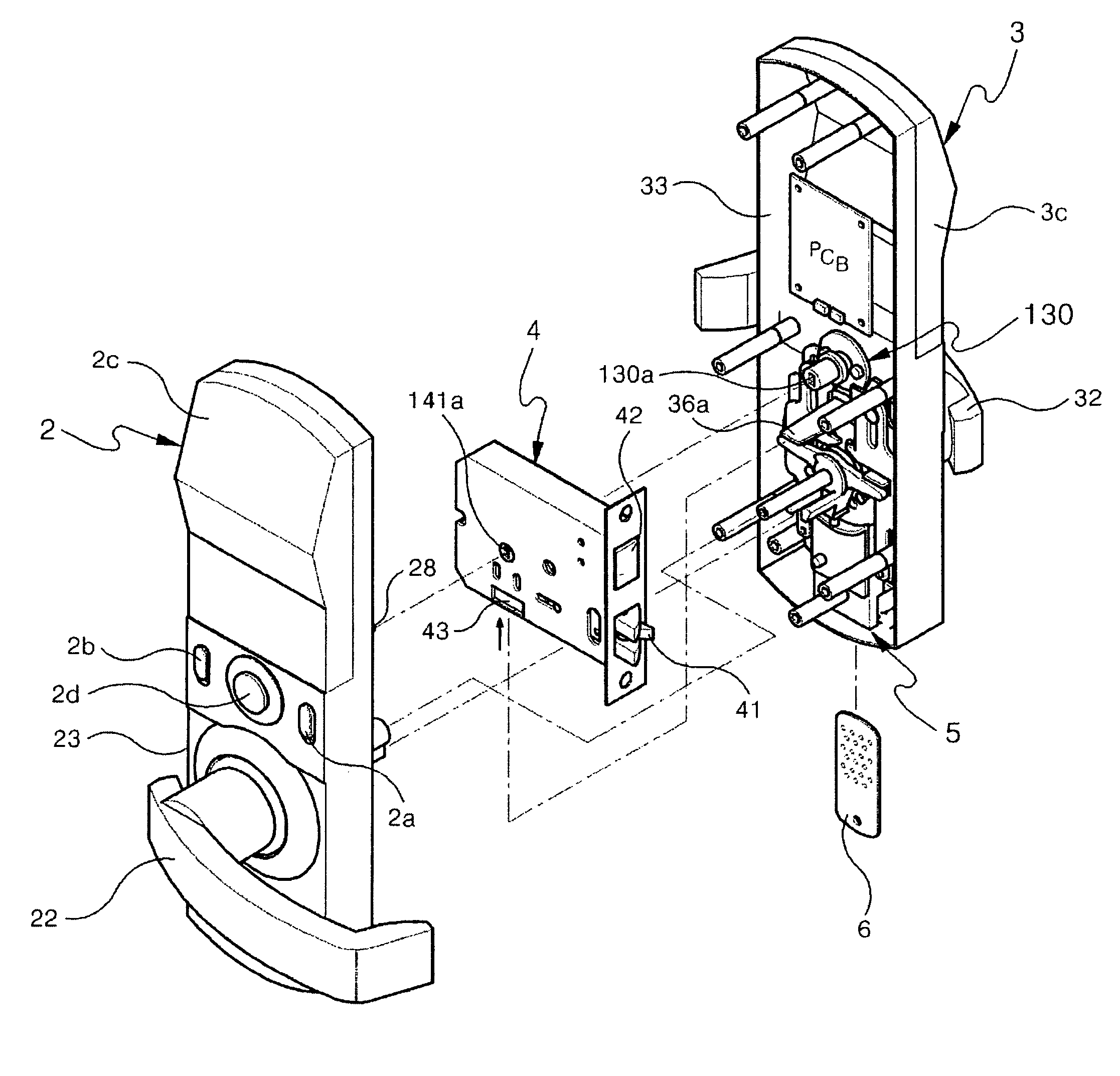
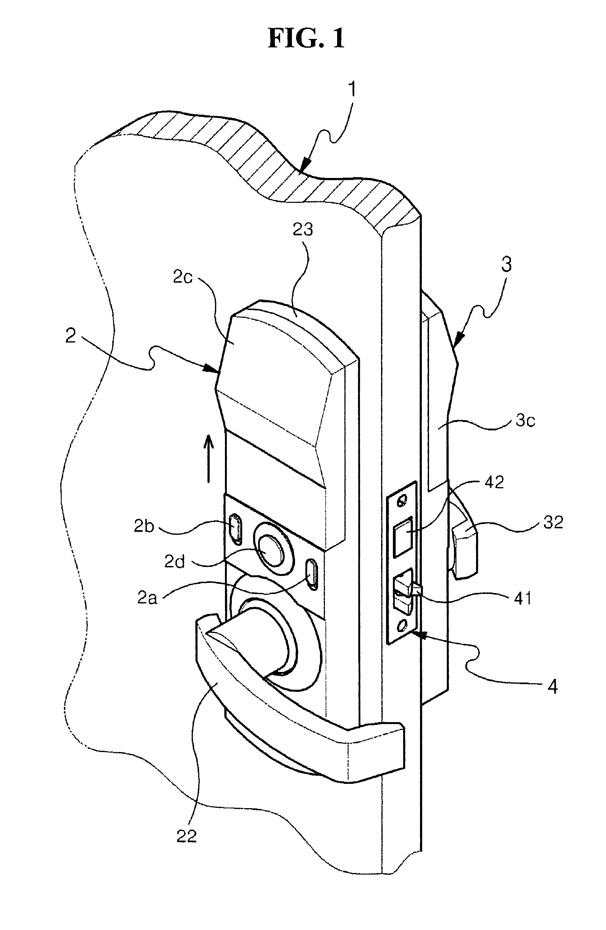
[0061]Referring to FIG. 1, the door locking apparatus of the present invention includes an inner unit 2 installed on one side of a door; and an outer unit 3 installed on the other side of the door 1 corresponding to the inner unit 2, wherein the inner and outer units 2,3 include door handles 22, 32, respectively. And, the mortise lock 4 including a latch bolt 41 and a dead bolt 42 mounted inside the door 1.

[0062]In the inner unit 2 and the outer unit 3 according to the present invention, nearly all components except for an insulator are prefe...


PUM


Abstract

An electronic door locking apparatus having a mortise lock including dead bolt and latch bolt installed therein, which is able to easily open a door from the outside by inserting a metal card having a magnet installed inside if a power source such as a dry battery is not supplied or if the locking apparatus is not useable due to other mechanical defects, and also able to perform a lock function since a dead bolt is locked if a door handle of an outer unit is rotated upwards when there are defects in a driving motor or electronic components. The door locking apparatus includes: a mortise lock having a dead bolt extended and retracted by a driving force of a motor installed in the inner unit in order to lock / unlock a door, and a door locking / unlocking latch bolt operated by the door handles of the inner and outer units; a latch bolt driver for operating the latch bolt; a dead bolt driver for operating the dead bolt; an emergency release assembly installed inside the outer unit and engaged with the door handle of the outer unit in order to unlock the locked dead bolt; and an emergency card inserted into the emergency release assembly to unlock the dead bolt.

Description

CLAIM OF PRIORITY[0001]This application makes reference to, incorporates the same herein, and claims all benefits accruing under 35 U.S.C. §119 from an application earlier filed in the Korean Intellectual Property Office on Nov. 30, 2006 and there duly assigned Serial No. 10-2006-0119564.BACKGROUND OF THE INVENTION[0002]1. Field of the Invention[0003]The present invention relates to an electronic door locking apparatus having a mortise lock installed therein, the mortise lock including a dead bolt and a latch bolt, and more particularly to an electronic door locking apparatus including a keypad, a fingerprint recognition device and a card reader, which can easily open a door from the outside by inserting a metal card having a magnet installed inside if a power source such as a dry battery is not supplied or if the locking apparatus is unusable due to other mechanical defects, and can also perform a lock function since a dead bolt is locked if a door handle of an outer unit is rotate...

Claims


Application Information

Patent Timeline
Patent Type & Authority Patents(United States)
IPC IPC(8): E05B47/00
CPCE05B13/005E05B47/0012E05B47/0043E05B59/00E05B2047/0017E05B2047/0031E05B2047/0086Y10S292/27Y10T70/5159Y10T70/5226Y10T70/5416Y10T70/5805Y10T70/5823Y10T70/7057Y10T70/7102Y10T70/7107Y10T70/8946Y10T292/0822Y10T292/0843Y10T292/0908Y10T292/57E05B49/00
Inventor HWANG, MOON SUNG
Owner KEICO HIGHTECH
Learn More