Simplified self-powered attitude survival indicator

a self-powered, survival indicator technology, applied in the direction of vehicle position/course/altitude control, process and machine control, instruments, etc., can solve the problem that failure of any of these power sources can render a gyroscopic attitude indicator inoperative, and achieve the effect of easy interpretation of aircraft attitude indication

Active Publication Date: 2010-11-02
JOYNER DANNY C
View PDF12 Cites 12 Cited by
  • Summary
  • Abstract
  • Description
  • Claims
  • Application Information

AI Technical Summary

Problems solved by technology

Failure of any of these power sources can render a gyroscopic attitude indicator inoperative.

Method used


Image

  • Simplified self-powered attitude survival indicator
  • Simplified self-powered attitude survival indicator
  • Simplified self-powered attitude survival indicator

Examples


Embodiment Construction

Indicators and Operation

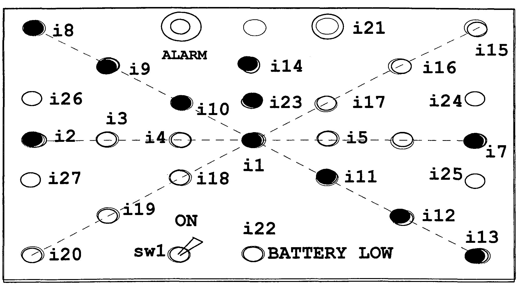
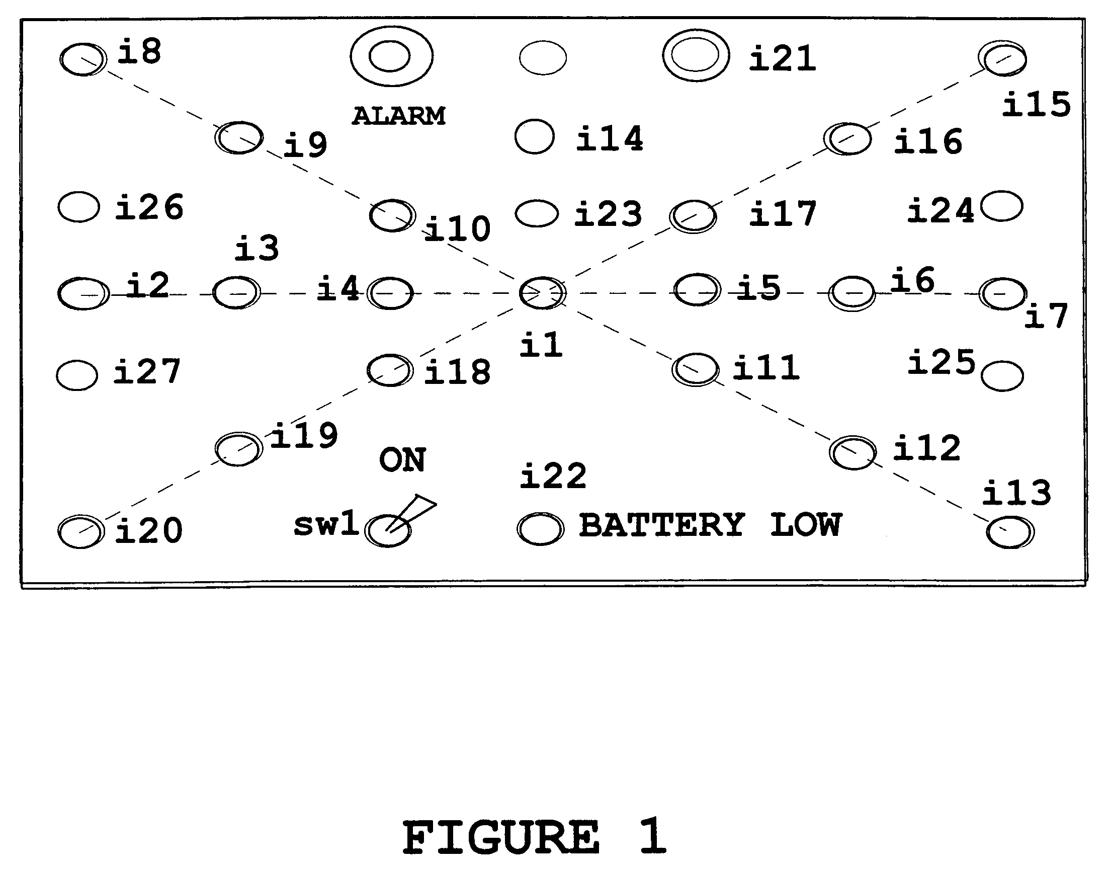
[0023]Referring to FIG. 1, there is illustrated the front panel display of the aircraft attitude indicator device of the present invention identifying the location of the different indicators, which are not numbered sequentially. When power is applied by the operation of SWI, the GREEN indicators (i14, i23, i1, i2, and i7) are illuminated. i2 and i7 represent a display of the reference attitude and i22 shows that the power is applied, but is of low voltage. This indicates that it is time to replace the internal batteries, or apply external power through J1, J2, and / or J3. Indicators i1, i23, and i14 represent the normal position of the rudder. The display of these indicators (i1, i23, and i14) is static when the aircraft changes attitude. Indicators i2 and 17 are fixed horizontal references. When the aircraft is flying straight and level, a plurality of GREEN indicators (i3, i4, i1, i5, i6 and i7), illustrated in FIG. 1, are presented as a full horizontal lin...


PUM


Abstract

This simplified self powered aircraft attitude survival indicator is easily and readily transportable from one aircraft to another and provides a simple indicator which gives a visual indication of aircraft attitude and alarms when the aircraft is in a dangerous attitude. The aircraft attitude indicator includes a housing containing a power source, multiple attitude sensors, and at least one piezoelectric alarm, and a front panel display with an arrangement of light emitting elements (electric bulbs or LEDs) providing visual attitude indicators.

Description

BACKGROUND OF THE INVENTION[0001]1. Field of the Invention[0002]This invention relates to self-powered gyroscopic and non-gyroscopic attitude indicators for use in personal or general aircraft, as well as Ultra-Light aircraft.[0003]2. Discussion of the Related Art[0004]Many devices have been developed to alert the pilot of an aircraft of changes in the attitude of the aircraft. These devices depend upon a gyroscopic device and resultant mechanical display of the horizon or attitude.[0005]Gyroscopic devices are usually powered by air flow, vacuum, or electric motors. Failure of any of these power sources can render a gyroscopic attitude indicator inoperative. The gyroscopic attitude indicators presently used in most aircraft are generally very accurate, and although they have been simplified over the passing years, it takes practice to understand the gyroscopic indicator and interpret the significance of the display. What is needed is a simple indicator which gives a visual indicatio...

Claims


Application Information

Patent Timeline
Patent Type & Authority Patents(United States)
IPC IPC(8): G08B23/00G06G7/00G06F19/00G06F7/70G06G7/76G01C5/00G05D1/08
CPCB64D43/02G01D2207/10
Inventor JOYNER, DANNY C.
Owner JOYNER DANNY C
Why Eureka
Try Eureka