Leg prosthesis system and method

a technology for prosthesis and legs, applied in the field of prosthesis systems, can solve the problems that conventional prosthesis systems are difficult to use for various activities, and achieve the effect of improving the quality of li

Active Publication Date: 2010-11-09
BARTLETT BRIAN
View PDF6 Cites 2 Cited by
  • Summary
  • Abstract
  • Description
  • Claims
  • Application Information

AI Technical Summary

Problems solved by technology

Conventional prosthesis systems can be difficult to use for various activities including some involving certain sports.

Method used


Image

  • Leg prosthesis system and method
  • Leg prosthesis system and method
  • Leg prosthesis system and method

Examples


Embodiment Construction

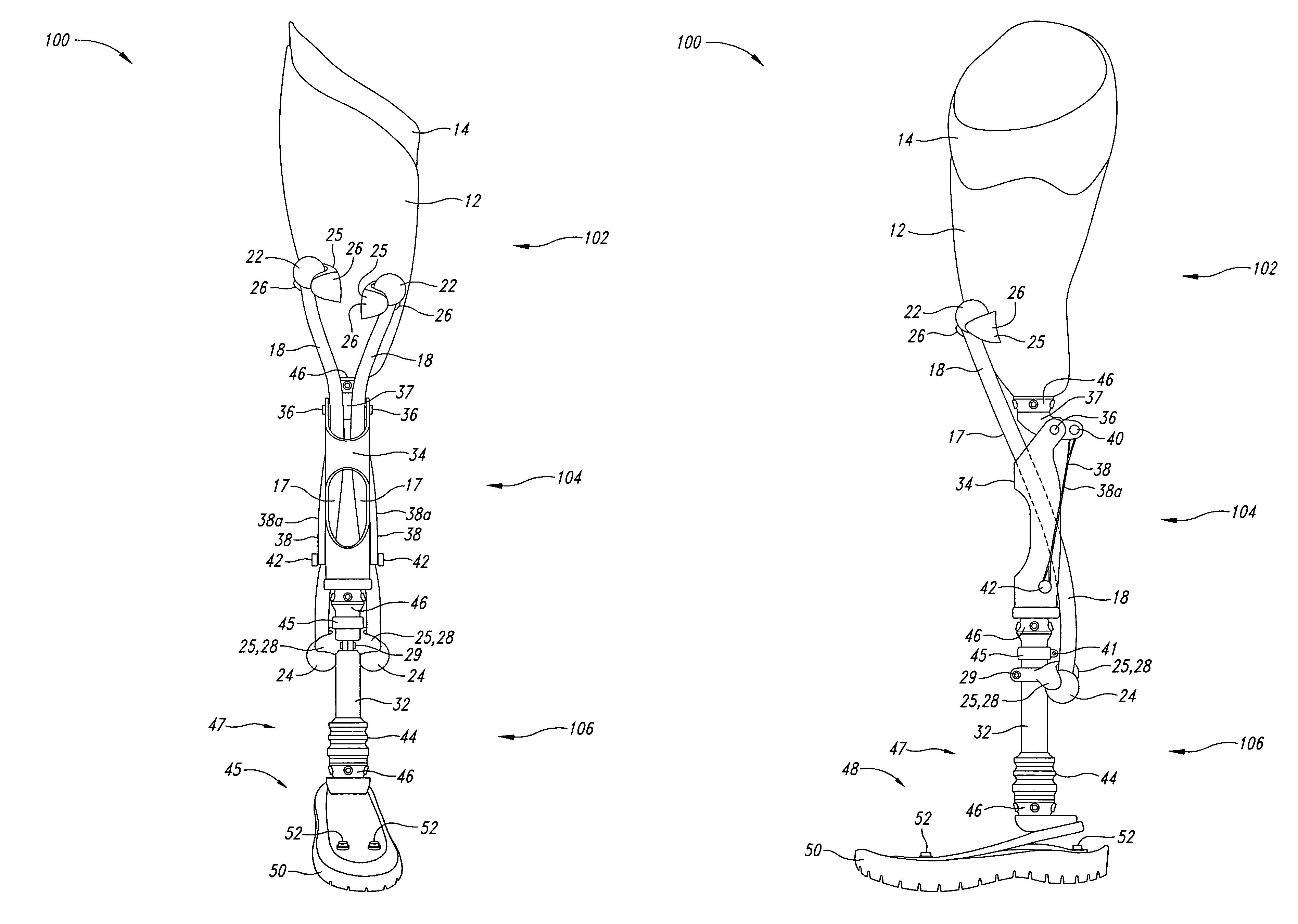
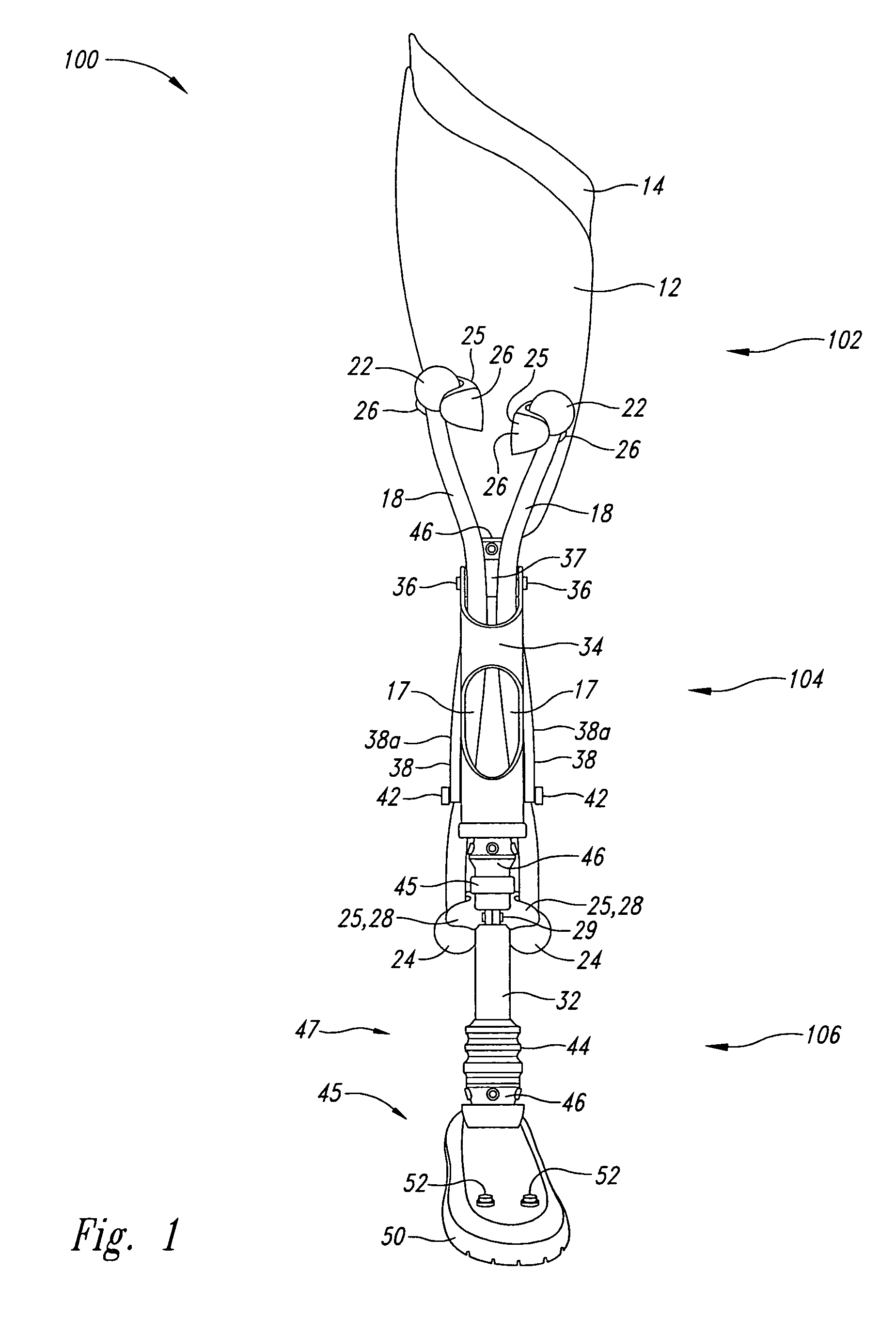
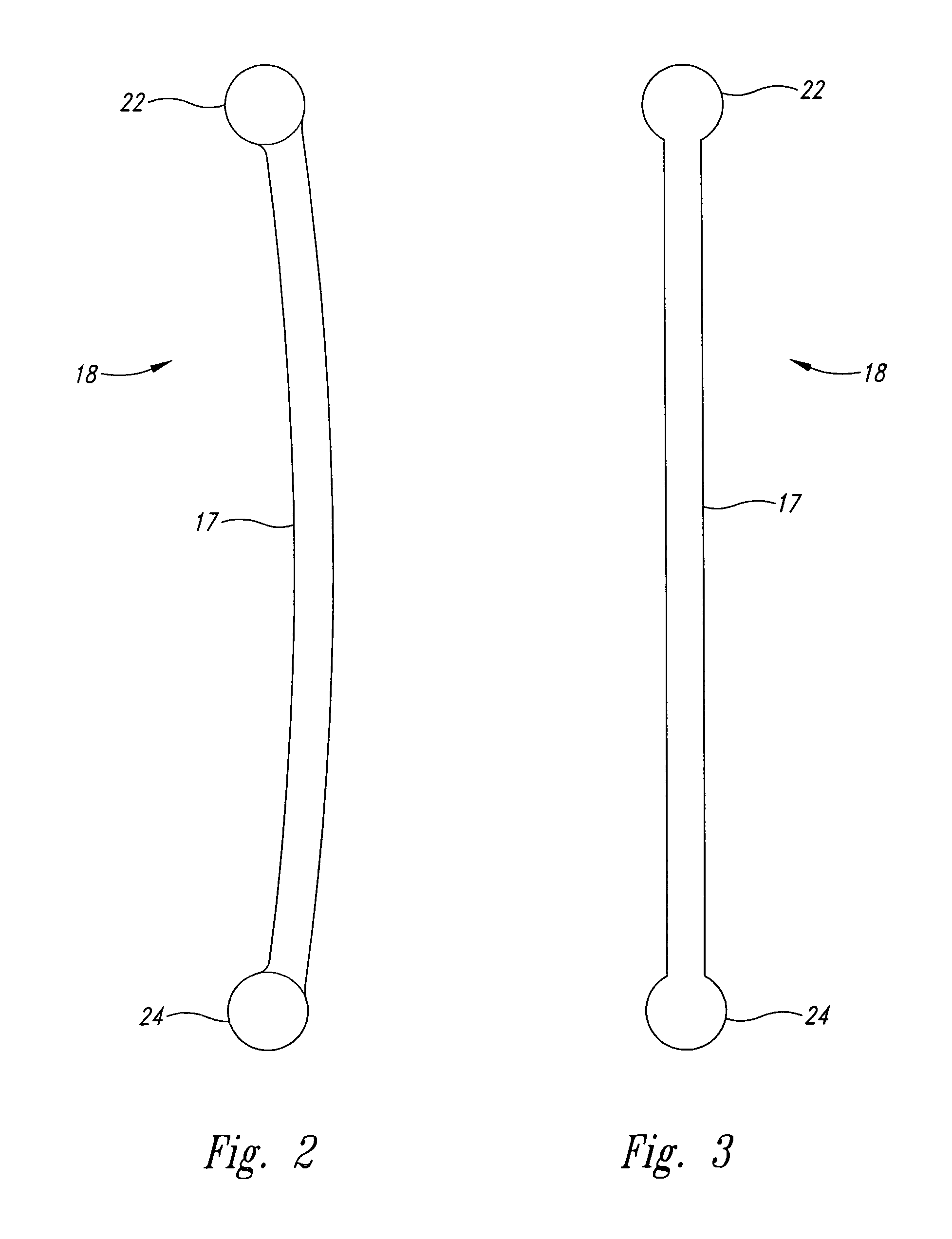
[0035]A prosthesis system described herein allows for energy to be stored and released via one or more elastic member(s). Based upon this approach potential exists for performance advantages over a conventional prosthesis, such as when used in activities requiring the use muscles such as extensor muscles, for instance, the quadriceps. Present implementations can have an advantageous use over conventional prostheses in many activities, including, but not limited to sports activities such as bicycling, surfing, wakeboarding, snowboarding, downhill skiing, cross country skiing, and waterskiing. The system includes, elastic member(s) that can store and release energy. The storing and releasing of energy in the elastic members happens during the movements made by the user and with the application of the user's own body weight while performing an activity. Implementations can also include a variety routing configurations for the elastic member(s), as well as a variety of mounting points t...


PUM


Abstract

A prosthesis system can have an advantageous use over conventional prostheses in certain activities, including, but not limited to certain sports activities: The system includes, elastic member(s) that can store and release energy. The storing and releasing of energy in the elastic members happens during the movements made by the user and with the application of the user's own body weight while performing an activity. Implementations can also include a variety of routing configurations for the elastic member(s), as well as a variety of mounting points to integrate the elastic member(s) into the system, and / or a variety of adjustable anti-hyperextension members, and / or a variety of interchangeable shoes used for applicable activities.

Description

BACKGROUND OF THE INVENTION[0001]1. Field of the Invention[0002]The present invention is directed generally to prosthesis systems.[0003]2. Description of the Related Art[0004]Conventional prosthesis systems can be difficult to use for various activities including some involving certain sports.BRIEF DESCRIPTION OF THE SEVERAL VIEWS OF THE DRAWINGS[0005]FIG. 1 is a front elevational view of an implementation of a prosthesis system shown in the resting position, having two elastic members routed through the knee frame, and shown with an adjustable strap acting as an anti-hyperextension member.[0006]FIG. 2 is a side elevational view of an elastic member.[0007]FIG. 3 is a front elevational view of the elastic member depicted in FIG. 2.[0008]FIG. 4 is a left elevational view of an implementation of the prosthesis system depicted in FIG. 1.[0009]FIG. 5 is a rear elevational view of an implementation of the prosthesis system depicted in FIG. 1.[0010]FIG. 6 is a right elevational view of an ...

Claims


Application Information

Patent Timeline
Patent Type & Authority Patents(United States)
IPC IPC(8): A61F2/68
CPCA61F2/60A61F2/64A61F2/6607A61F2/78A61F2/80A61F2002/5007A61F2002/5072A61F2002/5079A61F2002/6614
Inventor BARTLETT, BRIAN
Owner BARTLETT BRIAN
Why Eureka
Try Eureka