
Optimization of laser bar orientation for nonpolar and semipolar (Ga,Al,In,B)N diode lasers

a laser bar and laser bar technology, applied in the field of lasers, can solve the problems of difficult to engineer accurately emission characteristics, accumulate or deplete carriers at surfaces, etc., and achieve the effect of maximizing optical gain and maximizing optical gain

Active Publication Date: 2010-11-23
JAPAN SCI & TECH CORP
View PDF11 Cites 2 Cited by
  • Summary
  • Abstract
  • Description
  • Claims
  • Application Information

AI Technical Summary

Benefits of technology

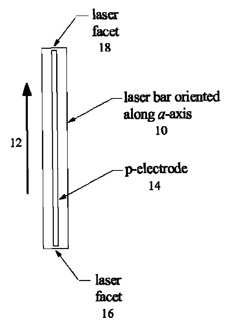
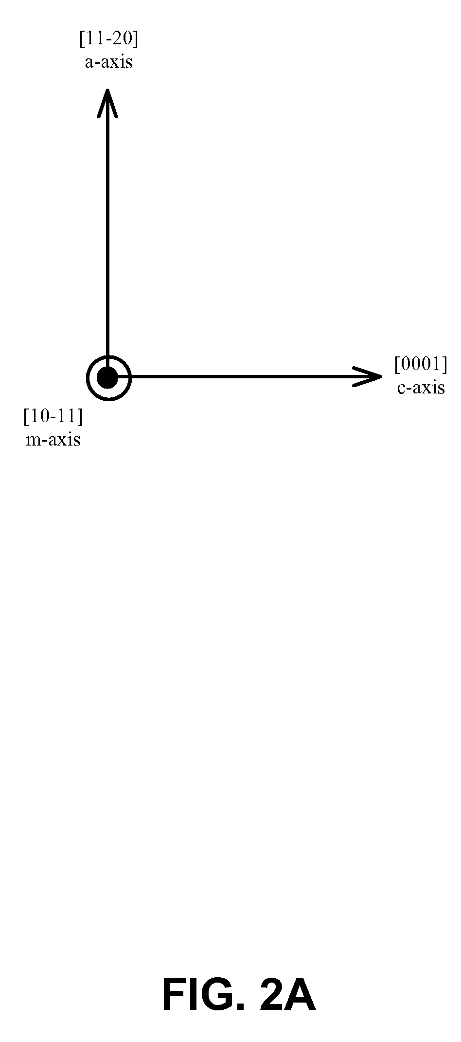
[0015]In this regard, the axis of light propagation is oriented substantially perpendicular to the optical polarization direction to maximize optical gain. Specifically, the axis of light propagation is oriented substantially along a c-axis of the nonpolar or semipolar Group-III nitride diode laser to maximize optical gain.

Problems solved by technology

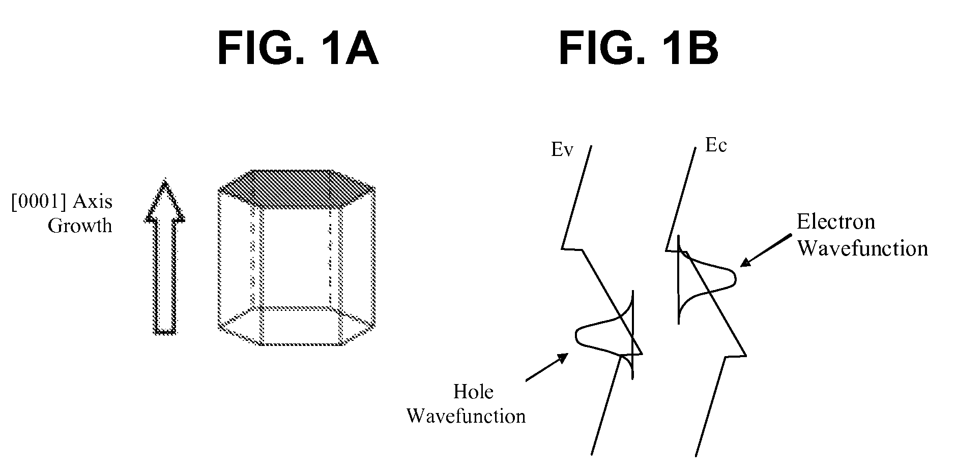
These discontinuities lead to the accumulation or depletion of carriers at surfaces and interfaces, which in turn produce electric fields.
5-6), making the emission characteristics difficult to engineer accurately.

Method used


Image

  • Optimization of laser bar orientation for nonpolar and semipolar (Ga,Al,In,B)N diode lasers
  • Optimization of laser bar orientation for nonpolar and semipolar (Ga,Al,In,B)N diode lasers
  • Optimization of laser bar orientation for nonpolar and semipolar (Ga,Al,In,B)N diode lasers

Examples


Embodiment Construction

[0026]In the following description of the preferred embodiment, reference is made to the accompanying drawings which form a part hereof, and in which is shown by way of illustration a specific embodiment in which the invention may be practiced. It is to be understood that other embodiments may be utilized and structural changes may be made without departing from the scope of the present invention.

[0027]Overview

[0028]The present invention is related to semiconductor materials, methods, and devices, and more particularly, to the growth and fabrication of a nonpolar or semipolar Group-III nitride diode laser, wherein the optical gain for the nonpolar or semipolar Group-III nitride diode laser is controlled by orienting the axis of light propagation in relation to the optical polarization direction resulting from the crystallographic orientation of the semiconductor materials used in the nonpolar or semipolar Group-III nitride diode lasers.

[0029]These nonpolar or semipolar Group-III nit...


PUM


Abstract

Optical gain of a nonpolar or semipolar Group-III nitride diode laser is controlled by orienting an axis of light propagation in relation to an optical polarization direction or crystallographic orientation of the diode laser. The axis of light propagation is substantially perpendicular to the mirror facets of the diode laser, and the optical polarization direction is determined by the crystallographic orientation of the diode laser. To maximize optical gain, the axis of light propagation is oriented substantially perpendicular to the optical polarization direction or crystallographic orientation.

Description

CROSS-REFERENCE TO RELATED APPLICATION[0001]This application claims the benefit under 35 U.S.C. Section 119(e) of the following and commonly-assigned U.S. patent application:[0002]U.S. Provisional Application Ser. No. 60 / 889,516, filed on Feb. 12, 2007, by Robert M. Farrell, Mathew C. Schmidt, Kwang Choong Kim, Hisashi Masui, Daniel F. Feezell, Daniel A. Cohen, James S. Speck, Steven P. DenBaars, and Shuji Nakamura, entitled “OPTIMIZATION OF LASER BAR ORIENTATION FOR NONPOLAR (Ga,Al,In,B)N DIODE LASERS,”[0003]which application is incorporated by reference herein.BACKGROUND OF THE INVENTION[0004]1. Field of the Invention[0005]The present invention relates to lasers, and in particular to optimization of laser bar orientation for nonpolar or semipolar (Ga,Al,In,B)N diode lasers.[0006]2. Description of the Related Art[0007](Note: This application references a number of different publications as indicated throughout the specification by one or more reference numbers within parentheses, e...

Claims


Application Information

Patent Timeline
Patent Type & Authority Patents(United States)
IPC IPC(8): H01S3/10
CPCB82Y20/00H01S5/20H01S5/32341H01S5/10H01S5/2201H01S5/3202H01S5/3404H01S5/34333H01S5/32025H01S5/320275
Inventor FARRELL, ROBERT M.SCHMIDT, MATHEW C.KIM, KWANG-CHOONGMASUI, HISASHIFEEZELL, DANIEL F.SPECK, JAMES S.DENBAARS, STEVEN P.NAKAMURA, SHUJI
Owner JAPAN SCI & TECH CORP
Learn More