Eureka AIR delivers breakthrough ideas for toughest innovation challenges, trusted by R&D personnel around the world.

Retaining gate for deep storage slot retention of storage cartridges

a technology for retaining gates and storage cartridges, which is applied in the direction of automatic cassette changing arrangements, instruments, data recording, etc., can solve the problem of very light force and achieve the effect of facilitating movemen

Inactive Publication Date: 2010-11-30
IBM CORP
View PDF7 Cites 21 Cited by
  • Summary
  • Abstract
  • Description
  • Claims
  • Application Information

AI Technical Summary

Benefits of technology

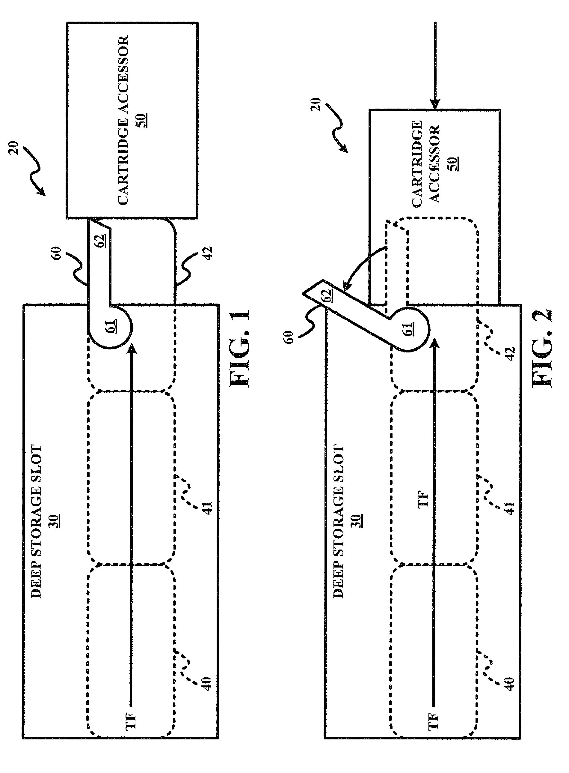
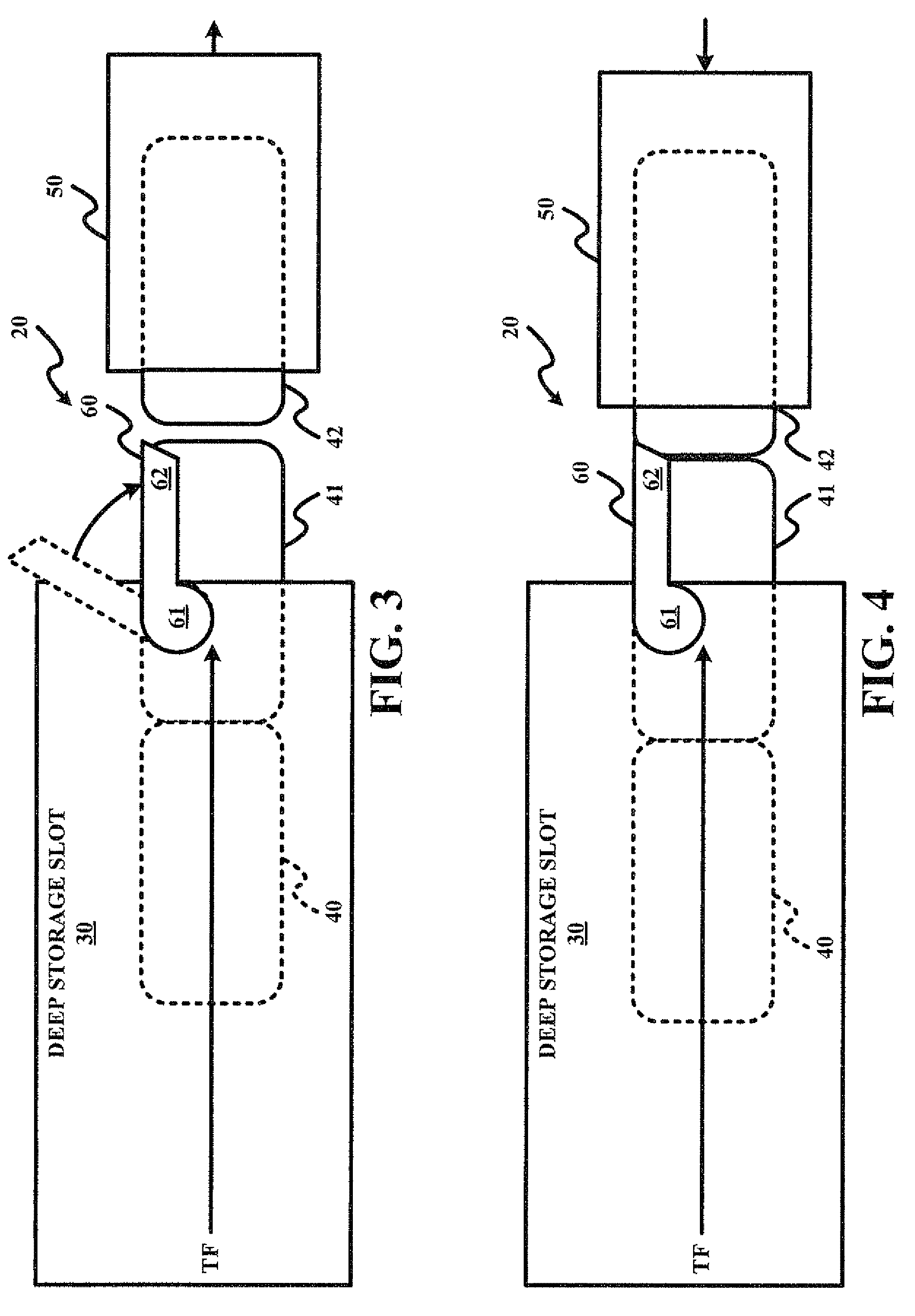
[0006]A first form of the present invention is a storage cartridge retention device comprising a deep storage slot and a retaining gate external to the deep storage slot. In operation, the deep storage slot stores one or more storage cartridge(s) through its front opening and biases the stored storage cartridge(s) in a direction of its front opening. The retaining gate is movable relative to the front opening of the deep storage slot between a retaining position and a releasing position. The retaining position engages a front storage cartridge to retain the storage cartridge(s) within the deep storage slot based on the bias of the storage cartridge(s) in the direction of the front opening of the deep storage slot, and the releasing position disengages the front storage cartridge to facilitate movement of the one storage cartridge(s) within the deep storage slot based on the bias of the storage cartridge(s) in the direction of the front opening of the deep storage slot.

Problems solved by technology

This method of retention is an adequate solution for retaining a single tape cartridge, but is deficient when deep storage slots with multiple cartridges are used.
A problem that has been seen with this solution is that when the retaining hooks have a flexible force that is movable by a cartridge accessor, this force becomes very light and the continuous force that moves the tape cartridges can overcome these retaining hooks, and push the tape cartridges through the hooks out of the slot.
A further complication with this solution is that when a tape cartridge is being removed from the deep storage slot by the cartridge accessor, the continuous force pushes the tape cartridges to the front on the deep storage slot simultaneously.

Method used


Image

  • Retaining gate for deep storage slot retention of storage cartridges
  • Retaining gate for deep storage slot retention of storage cartridges
  • Retaining gate for deep storage slot retention of storage cartridges

Examples


Embodiment Construction

[0014]The present invention is premised on providing a retention gate that is externally attached to a deep storage slot relative to a front opening of the deep storage slot whereby the retaining gate can be activated by a cartridge accessor of an automated tape library. The retaining gate allows for positive cartridge retention, and ensures that one or more storage cartridges do not get pushed out of the deep storage slot simultaneously while allowing the pushing mechanism of the deep storage slot to always push the storage cartridge(s) to the opening in a deep storage slot.

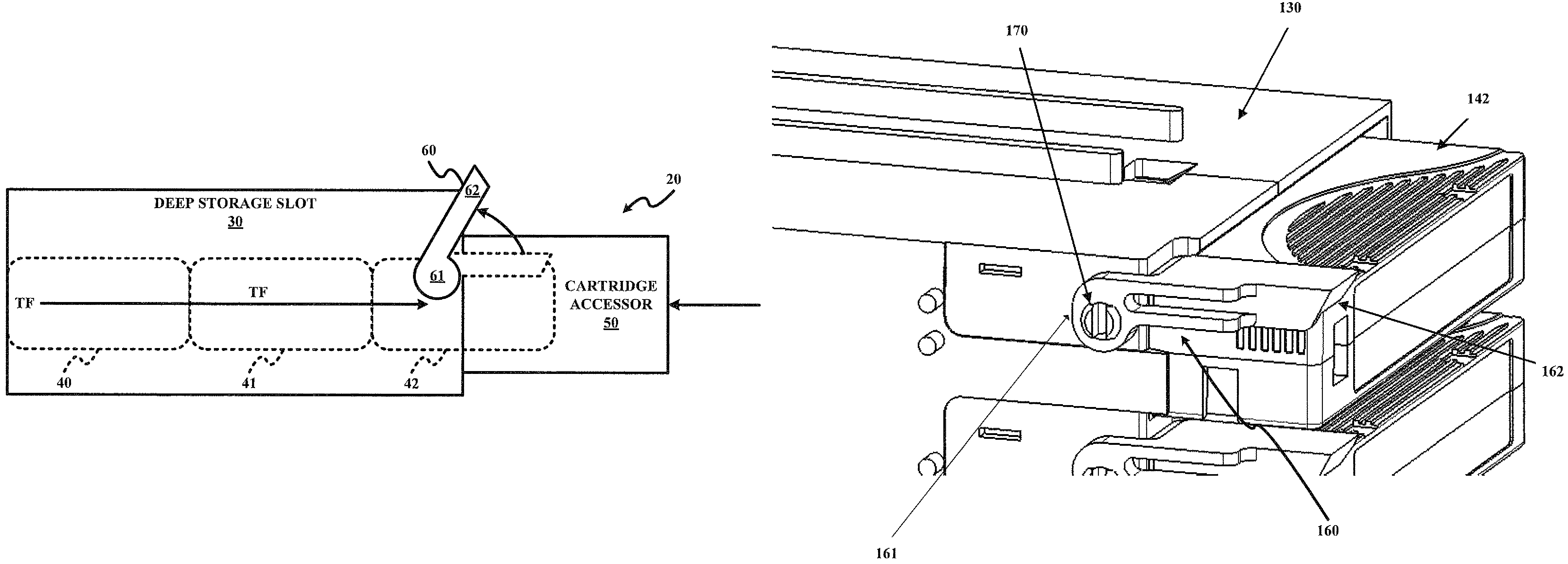
[0015]The basic working of the retaining gate is that the gate prevents the storage cartridge(s) from being pushed out of a deep storage slot. For example, as shown in FIGS. 1-4, a retaining gate 60 can be lifted by a cartridge accessor50 or by a front cartridge 42 for cartridge removal from / insertion into a deep storage slot 30. Specifically, retaining gate 60 has a pivoting arm 61 mounted on deep storage slot ...


PUM

PropertyMeasurementUnit
movementaaaaaaaaaa
storage densityaaaaaaaaaa
depthaaaaaaaaaa

Abstract

A storage cartridge retention device employs a deep storage slot for storing one or more storage cartridge(s) through its front opening and biases the stored storage cartridge(s) in a direction of its front opening. The storage cartridge retention device further employs a retaining gate external to the deep storage slot and movable relative to the front opening of the deep storage slot between a retaining position and a releasing position. The retaining position engages a front storage cartridge to retain the storage cartridge(s) within the deep storage slot based on the bias of the storage cartridge(s) in the direction of the front opening of the deep storage slot, and the releasing position disengages the front storage cartridge to facilitate movement of the one storage cartridge(s) within the deep storage slot based on the bias of the storage cartridge(s) in the direction of the front opening of the deep storage slot.

Description

FIELD OF THE INVENTION[0001]The present invention generally relates to a retention of storage cartridges within a deep storage slot (e.g., retention of multiple tape cartridges within a storage slot capable of holding the tape storage cartridges in a sequential alignment). The present invention specifically relates to a retaining gate for retaining storage cartridges within a deep storage slot during an insertion by a cartridge accessor of a front storage cartridge into the deep storage slot or a retrieval by a cartridge accessor of a front storage cartridge from the deep storage slot.BACKGROUND OF THE INVENTION[0002]A method for increasing storage density and capacity in automated tape libraries is to stack tape cartridges in depth, one behind the other. The slots that hold these tape cartridges can be described as deep storage slots that allow for more than one tape cartridge to be stored in depth. Deep storage slots require a pushing mechanism to push a tape cartridge to the fron...

Claims


Application Information

Patent Timeline
Patent Type & Authority Patents(United States)
IPC IPC(8): G11B15/675
CPCG11B17/225
Inventor NAVE, SHAWN M.YARDY, RAYMOND
Owner IBM CORP
Why Eureka
Eureka Blog
Learn More