Ultra high speed uniform plasma processing system

a plasma processing system and high-speed technology, applied in the field of processing apparatus, can solve the problems of increasing the volume and the footprint of the processing system, affecting the processing system, and relying on conventional parallel-plate electrodes

Inactive Publication Date: 2010-12-07
NORDSON CORP
View PDF18 Cites 176 Cited by
  • Summary
  • Abstract
  • Description
  • Claims
  • Application Information

AI Technical Summary

Problems solved by technology

Plasma processing systems that rely on conventional parallel-plate type electrodes may experience process non-uniformities across the surface of relatively large substrates positioned in a processing region defined between the electrodes for processing.
The non-uniformity may be particularly significant at the peripheral edges of the processing region.
Among other disadvantages, this increases the chamber volume and the footprint of the processing system.
In particular, these are especially undesirable effects that significantly reduce throughput in in-line plasma processing systems intended to serially plasma process large quantities of substrates, which requires periodic evacuation and venting to exchange substrates after each processing cycle.
Another disadvantage of conventional plasma processing systems is that plasma is inadvertently generated in evacuated regions inside the processing chamber peripheral to the processing region between the electrodes.
The generation of plasma in these regions renders the plasma process difficult to control and may damage components positioned within these regions.
This unconfined plasma may also change the location of power absorbed by the plasma within the plasma processing chamber, thereby making it difficult to control the delivery of power to the electrodes to achieve consistent and reproducible processing.

Method used


Image

  • Ultra high speed uniform plasma processing system
  • Ultra high speed uniform plasma processing system
  • Ultra high speed uniform plasma processing system

Examples


Embodiment Construction

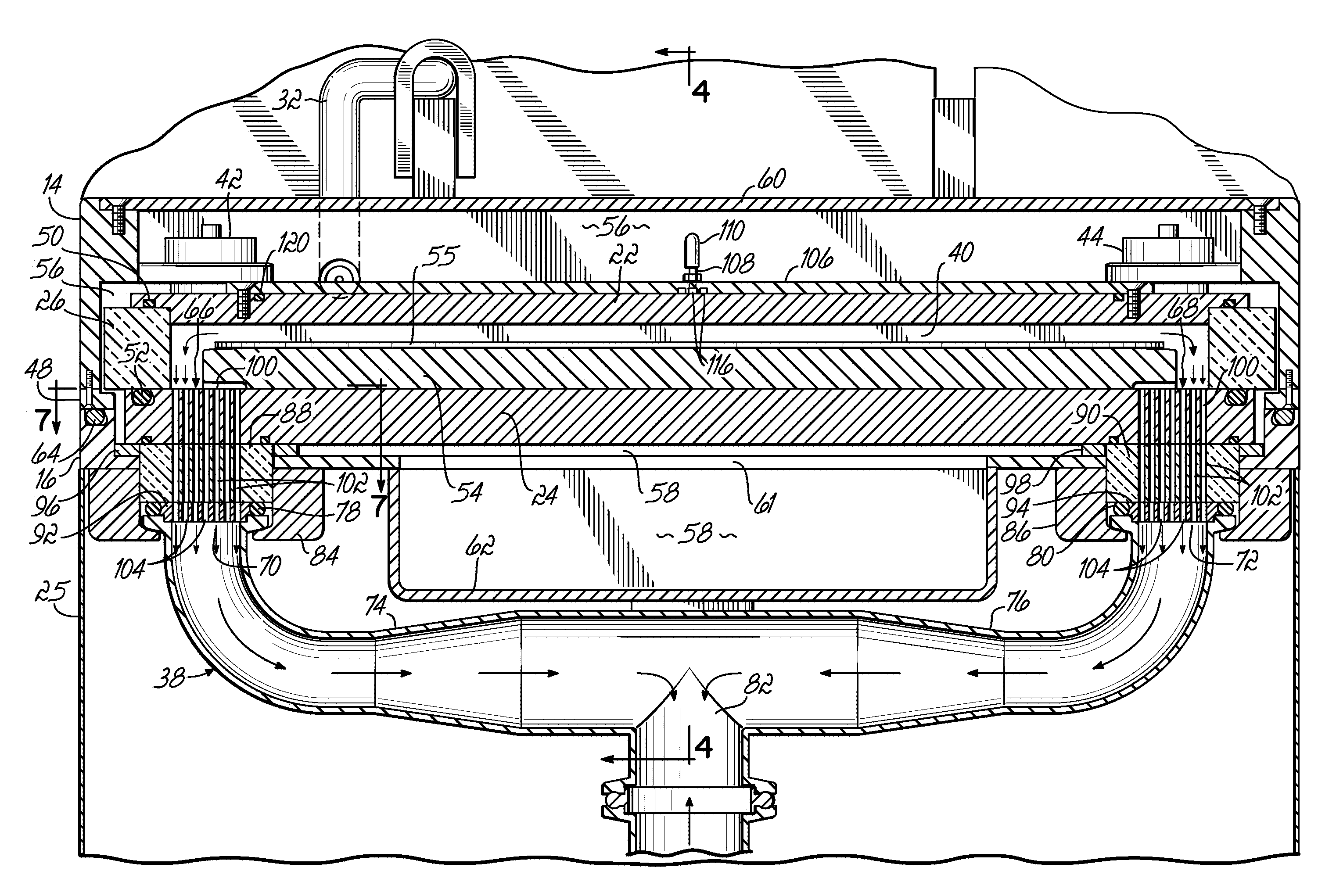
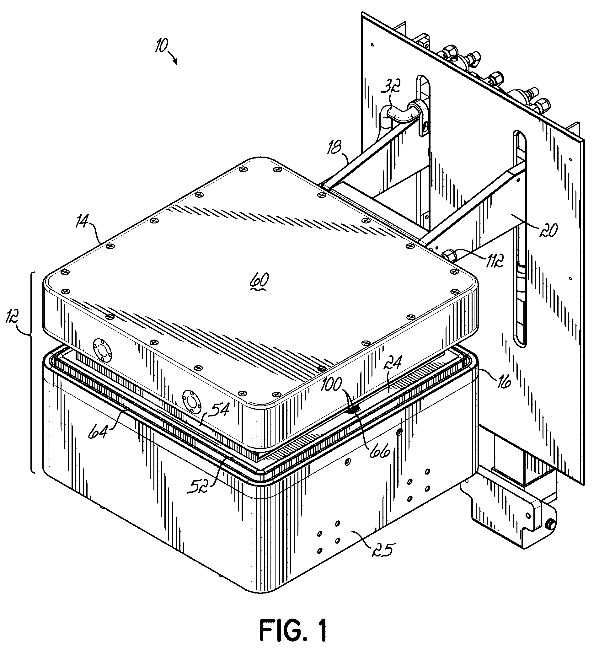
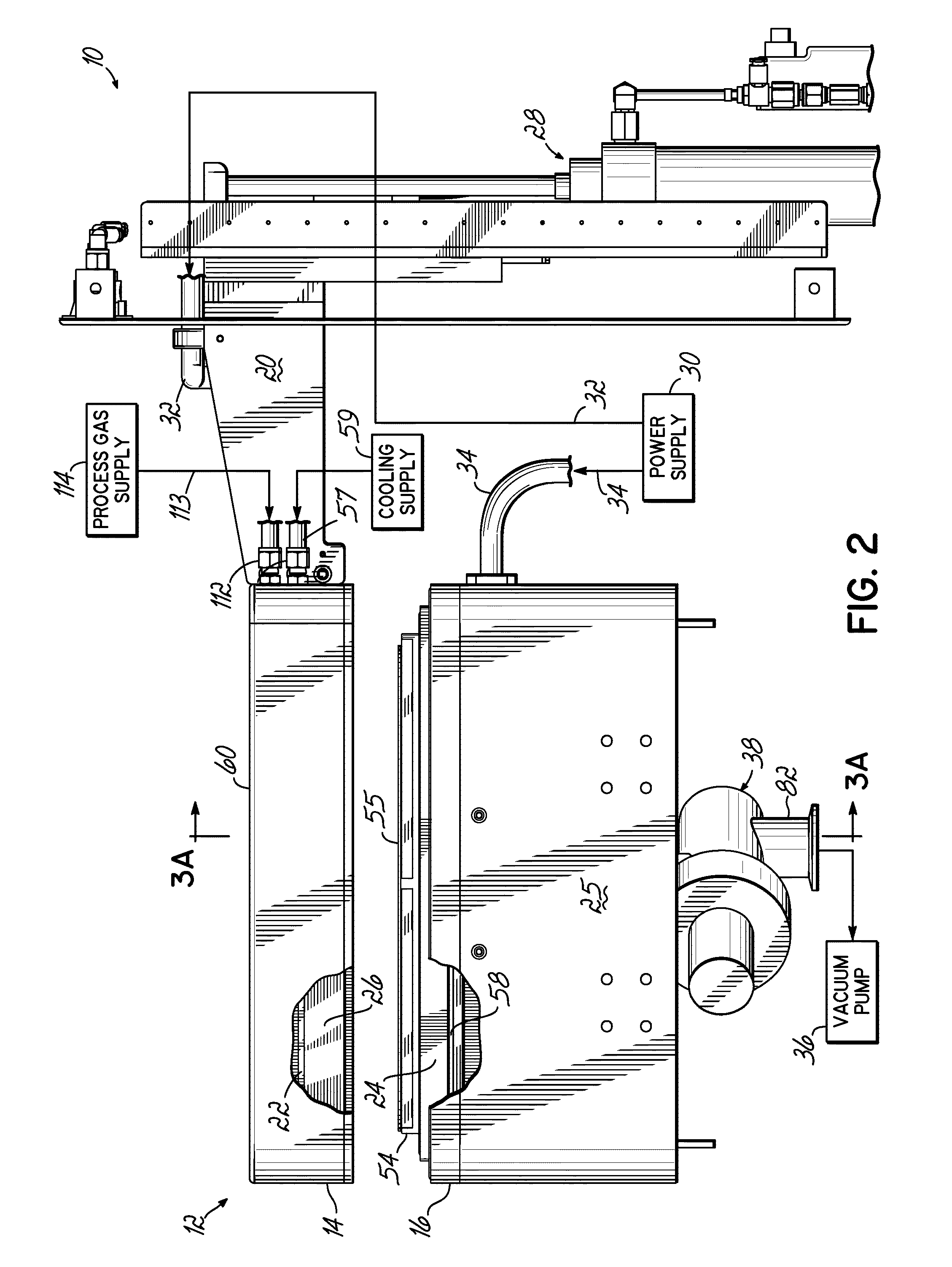
[0021]With reference to FIGS. 1 and 2, a plasma processing system 10 generally includes an enclosure 12 having a lid 14 and a base 16 upon which the lid 14 rests, a pair of support arms 18, 20 depending from the lid 14, an upper electrode 22, and a lower electrode 24. The processing system 10 further includes a separating member or ring 26 positioned between the upper and lower electrodes 22, 24 and contacting confronting faces about the perimeter of the upper and lower electrodes 22, 24. The confronting faces of the electrodes 22, 24 are generally planar and parallel plates and have approximately identical surface areas. A shroud 25 extends downwardly from the base 16 toward the surface supporting system 10.

[0022]Mechanically coupled with the support arms 18, 20 is a lifting device 28, illustrated as a pneumatic cylinder, that vertically lifts and lowers the lid 14 relative to the base 16 between a raised position (FIG. 3A) and a lowered position (FIG. 3B). In the raised position, ...


PUM

PropertyMeasurementUnit
frequencyaaaaaaaaaa
frequencyaaaaaaaaaa
frequencyaaaaaaaaaa

Abstract

An apparatus for processing a substrate with a plasma. The apparatus includes first and second electrodes positioned with a spaced apart relationship. A separating ring has a vacuum-tight engagement with confronting surfaces of the first electrode and the second electrode to define an evacuatable processing region therebetween. Communicating with the processing region is a process gas port for introducing a process gas to the processing region. The processing region may be evacuated through a vacuum port defined in one of the first and second electrodes to a pressure suitable for exciting a plasma from the process gas in the processing region when the first and second electrodes are powered.

Description

FIELD OF THE INVENTION[0001]The invention generally relates to processing apparatus for processing substrates with a plasma.BACKGROUND OF THE INVENTION[0002]Plasma processing systems are commonly used for modifying the surface properties of substrates in various industrial applications. For example, plasma processing systems are routinely used to plasma treat the surfaces of integrated circuits, electronic packages, and printed circuit boards in semiconductor applications, solar panels, hydrogen fuel cell components, automotive components, and rectangular glass substrates used in flat panel displays. Plasma processing systems are also used in medical applications to modify the surface properties of devices, such as stents and implants, inserted into the human body. Plasma processing systems that rely on conventional parallel-plate type electrodes may experience process non-uniformities across the surface of relatively large substrates positioned in a processing region defined betwee...

Claims


Application Information

Patent Timeline
Patent Type & Authority Patents(United States)
IPC IPC(8): C23C16/50C23C16/503C23C16/509C23F1/00H01L21/306C23C16/06C23C16/22
CPCH01J37/32633H01J37/32834
Inventor CONDRASHOFF, ROBERT S.FAZIO, JAMES P.GETTY, JAMES D.TYLER, JAMES S.
Owner NORDSON CORP
Why Eureka
Try Eureka