Portable urinal with a shaped inlet and a membrane valve

a urinal and membrane valve technology, applied in the field of portable urinals, can solve the problems of urine coming into contact, urine backflow, undesirable spillage, etc., and achieve the effect of resisting backflow and undesirable spillage of urin

Active Publication Date: 2010-12-07
ABBATO TOMASINE
View PDF13 Cites 8 Cited by
  • Summary
  • Abstract
  • Description
  • Claims
  • Application Information

AI Technical Summary

Benefits of technology

[0013]It is an object of this invention to provide a portable urinal that effectively resists backflow and undesirable spillage of urine from the urinal onto the patient or the patient's bed or both.
[0014]It is a further object of this invention to provide a portable urinal that resists the gathering of a liquid in a recess in an exterior region of the portable urinal.

Problems solved by technology

Backflow is a long recognized problem associated with portable urinals.
Backflow, or undesirable spillage, of urine may occur during use or while handling the filled portable urinal.
Backflow can result in the urine coming into contact with the person handling the portable urinal or the patient's bed in.
Such backflow can cause unsanitary health conditions and result in the increased risk for further medical problems, such as infections.
In addition, the workload of caretakers is increased due to the need for cleaning the patient and / or the bed following the spillage of urine thereon.
Mishandling of the urinal may be a result of the bedridden patient leaving the urinal, for example, on the bed following use and then inadvertently contacting the urinal and causing spillage therefrom.
These devices, however, each have a disadvantage.
Such flapper valves may create a liquid gathering recess at the contact point of the flapper and the tube when the flow of liquid is insufficient to overcome the bias of the spring.
This collection apparatus is not convenient for portable use, such as by a bedridden patent, and is not well suited for resisting spillage of urine contained in the collection apparatus.
This fluid, which never passes through the valve, is very likely to spill out of the portable urinal.
Second, the membrane tends to be very thin, and therefore, flimsy.
Even when a bead of material is provided about the perimeter of the membrane as a reinforcement, the single central attachment fails to provide a sufficient amount of support to ensure that the membrane seals the openings.

Method used


Image

  • Portable urinal with a shaped inlet and a membrane valve
  • Portable urinal with a shaped inlet and a membrane valve
  • Portable urinal with a shaped inlet and a membrane valve

Examples


Embodiment Construction

[0024]As used herein, “interior” and “exterior” are used in relation to locations on either side of the valve assembly and / or reservoir. That is, at a location where a liquid is trapped by the valve assembly is an interior location. Whereas “inner” and “outer” are used in relation to the area enclosed by the valve assembly, spout, and / or reservoir. For example, a liquid disposed within the reservoir is both on the inner side of the reservoir and on the interior side of the valve assembly. Conversely, a liquid within the spout is on the inner side of the spout but on the exterior side of the valve assembly.

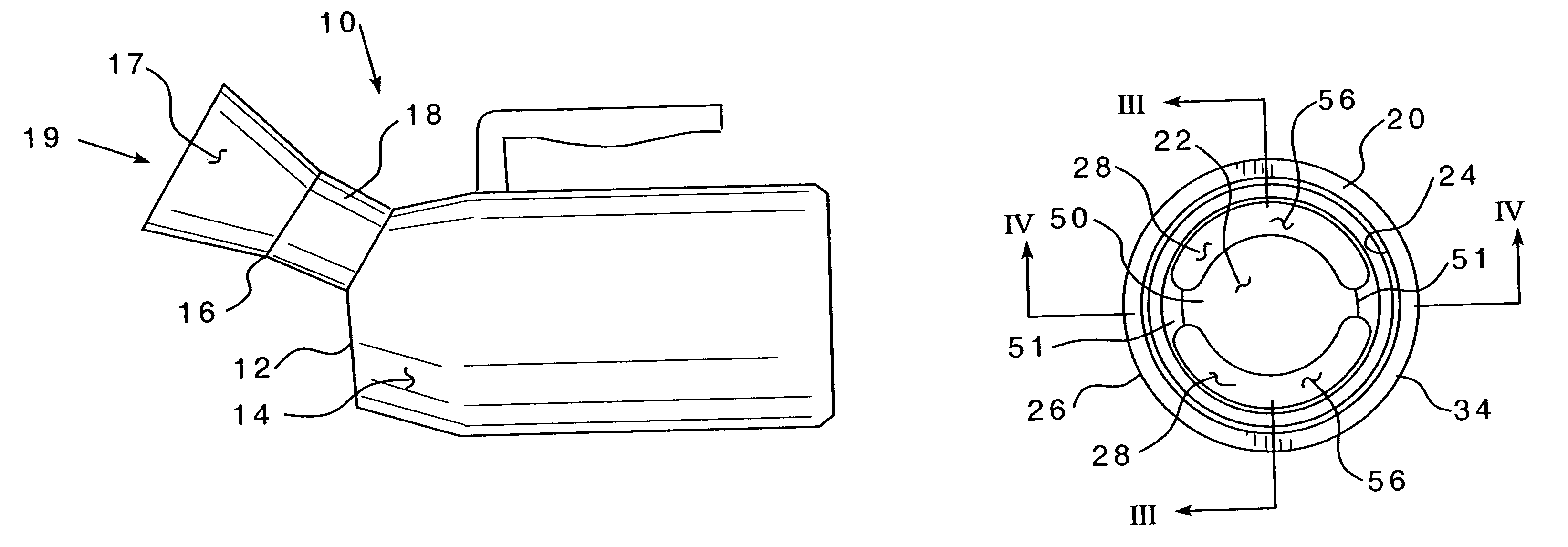
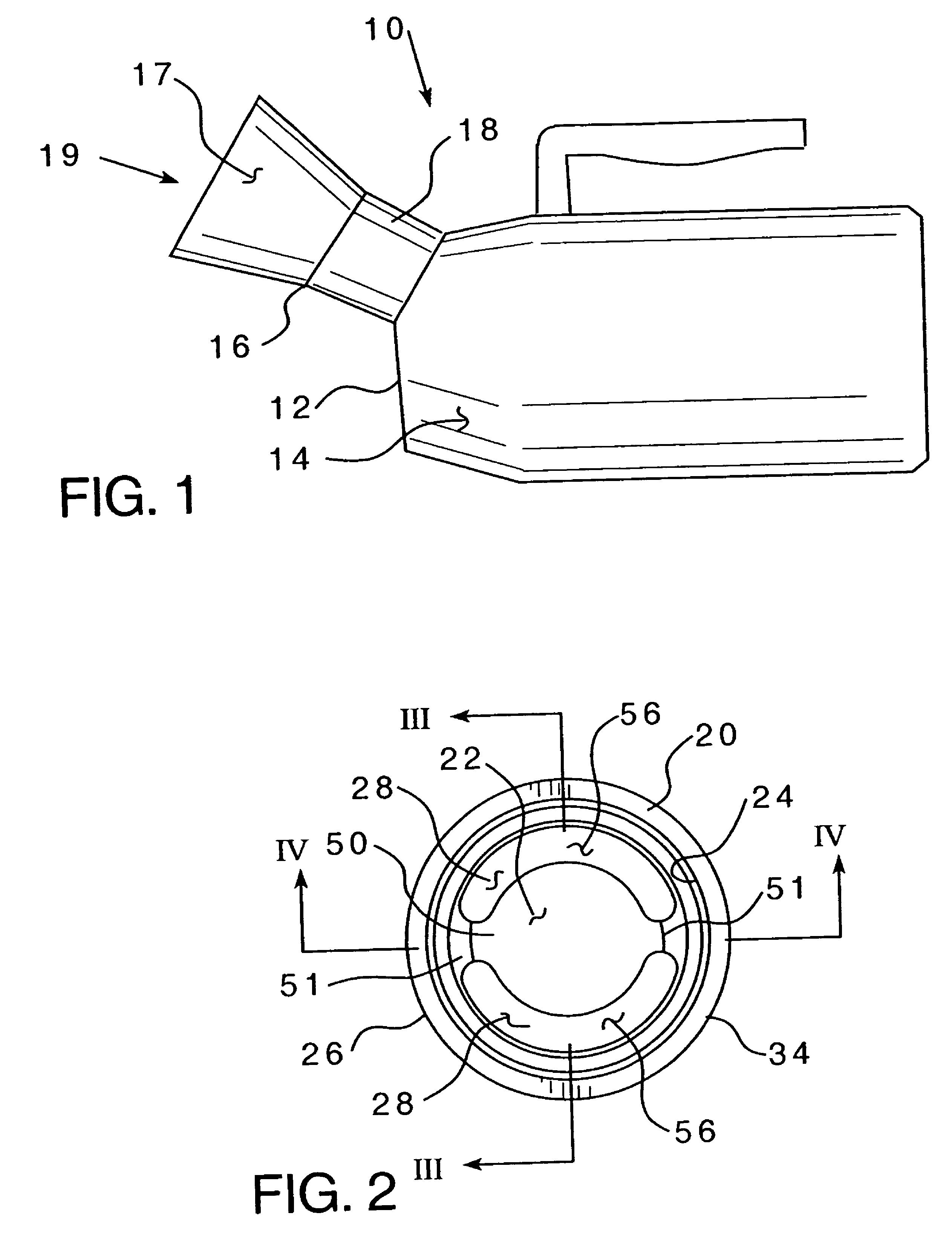
[0025]As shown in FIG. 1, a portable urinal 10 includes a waterproof container 12 that defines a reservoir 14 and a spout 16. The container 12 may be either a flexible material or a rigid material. The spout 16 defines an inlet 17 that provides a means of fluid communication for a liquid to travel from the outside to the reservoir 14. Within the spout is a valve assembly 18. Thus, ...


PUM


Abstract

A portable urinal that includes a container defining a liquid reservoir and a spout extending therefrom. The spout has an inlet for receiving a liquid. A valve assembly is disposed within the spout. The valve assembly has an interior region and an exterior region. The valve assembly includes a sidewall and one or more sealable openings for permitting flow of a liquid into the reservoir, while resisting undesired flow of the liquid out of the reservoir. The openings defining the line between the interior region and the exterior region. The valve assembly sidewall has a shaped contour structured to direct liquid flow into the openings.

Description

CROSS REFERENCE TO RELATED APPLICATION[0001]This application claims priority under 35 U.S.C. §119(e) to provisional Application Ser. No. 60 / 425,921, filed Nov. 13, 2002, incorporated by reference.BACKGROUND OF THE INVENTION[0002]1. Field of the Invention[0003]The present invention relates generally to portable urinals, and more specifically, to a portable male urinal having a valve assembly with a shaped inlet which directs urine to flow into a reservoir, and a membrane that resists backflow or spillage of the urine following use of the urinal.[0004]2. Background Information[0005]Portable urinals are used by those who need to urinate but cannot access a toilet, for example, patients confined to bed or pilots in light aircraft. Typically, such urinals include a urine receiving reservoir and a spout extending therefrom. The spout includes an inlet through which the urine is received and typically contains a valve structured to resist backflow.[0006]Backflow is a long recognized proble...

Claims


Application Information

Patent Timeline
Patent Type & Authority Patents(United States)
IPC IPC(8): A61M1/00A47K11/00F16K21/04
CPCA61G9/006Y10T137/784
Inventor ABBATO, TOMASINE
Owner ABBATO TOMASINE
Why Eureka
Try Eureka