
Tile with wide coupling configuration and method for the same

a technology of wide coupling and tile, applied in the field of tiles, can solve the problems of many people being injured, concrete flooring is easy to construct and provide long-term wear, and concrete provides no “give” during us

Active Publication Date: 2010-12-14
CONNOR SPORT COURT INT
View PDF112 Cites 38 Cited by
  • Summary
  • Abstract
  • Description
  • Claims
  • Application Information

AI Technical Summary

Benefits of technology

This design simplifies the installation process by providing a clear and secure method for aligning and attaching tiles, reducing the likelihood of errors and speeding up the formation of a modular floor covering, while allowing for easy identification and alignment of coupling parts.

Problems solved by technology

For example, concrete flooring is easy to construct and provides long term wear.
However, the concrete provides no “give” during use and many people are injured each year during sporting events due to falls and other mishaps.
The wood floors, however, are expensive to install and require continued maintenance to keep them in good condition.
If a tile is damaged it may easily be replaced.
One problem with synthetic flooring involves the time consuming nature of installation.
When installing a large floor covering with hundreds, and even thousands, of tiles, coupling each of the tiles is long and laborious task.
The numerous amounts of couplings for each of the tiles often results in the installer miss-attaching some of the couplings due to human error and fatigue.
Further, the miss-attached couplings are often not readily identifiable.
It is often difficult for the installer to identify, properly align and mate the proper corresponding tiles, resulting in offsetting the couplings and tiles between adjacent columns.
Further, tiles of one column may become spaced slightly different with respect to the tiles in another column, resulting in different lengths in the columns and miss-alignment of the couplings between the adjacent columns.
As a result, proper interconnection of the couplings of the tiles is very time consuming.

Method used


Image

  • Tile with wide coupling configuration and method for the same
  • Tile with wide coupling configuration and method for the same
  • Tile with wide coupling configuration and method for the same

Examples


Embodiment Construction

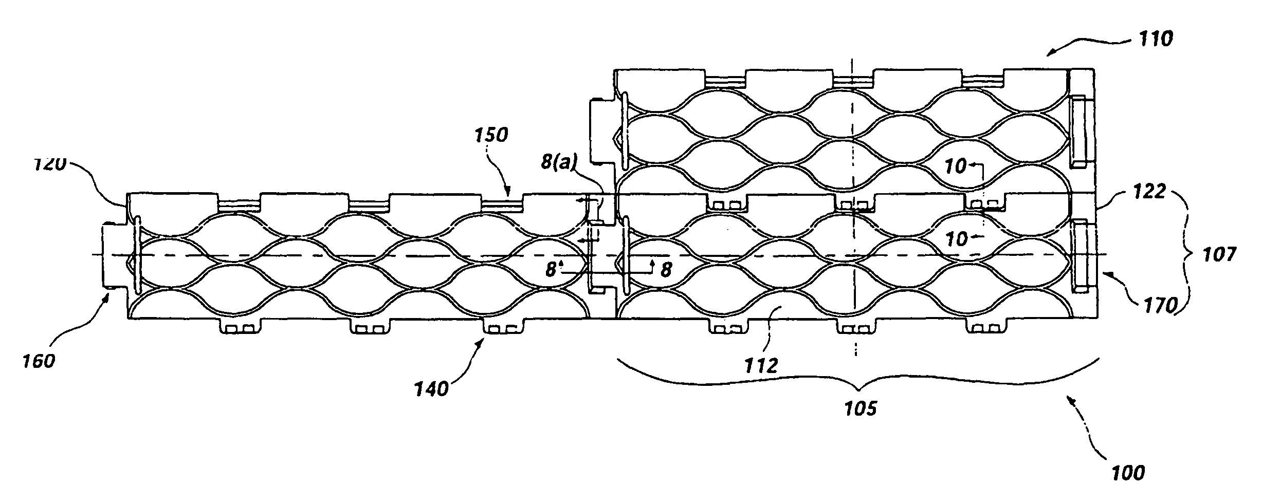
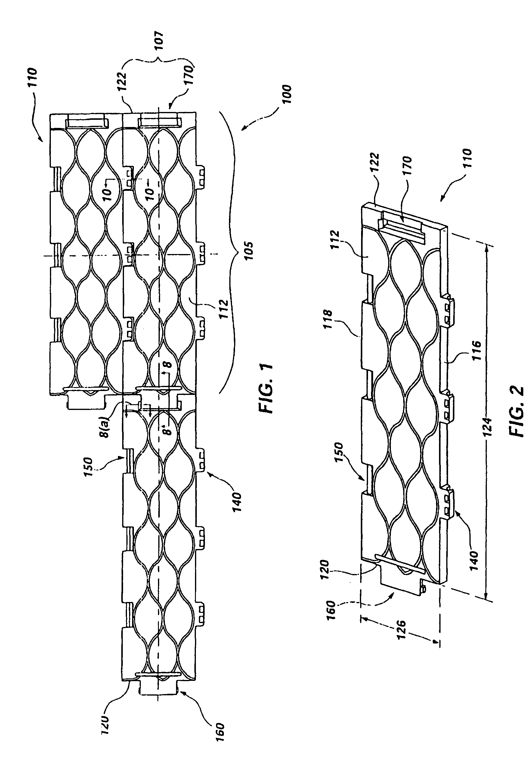
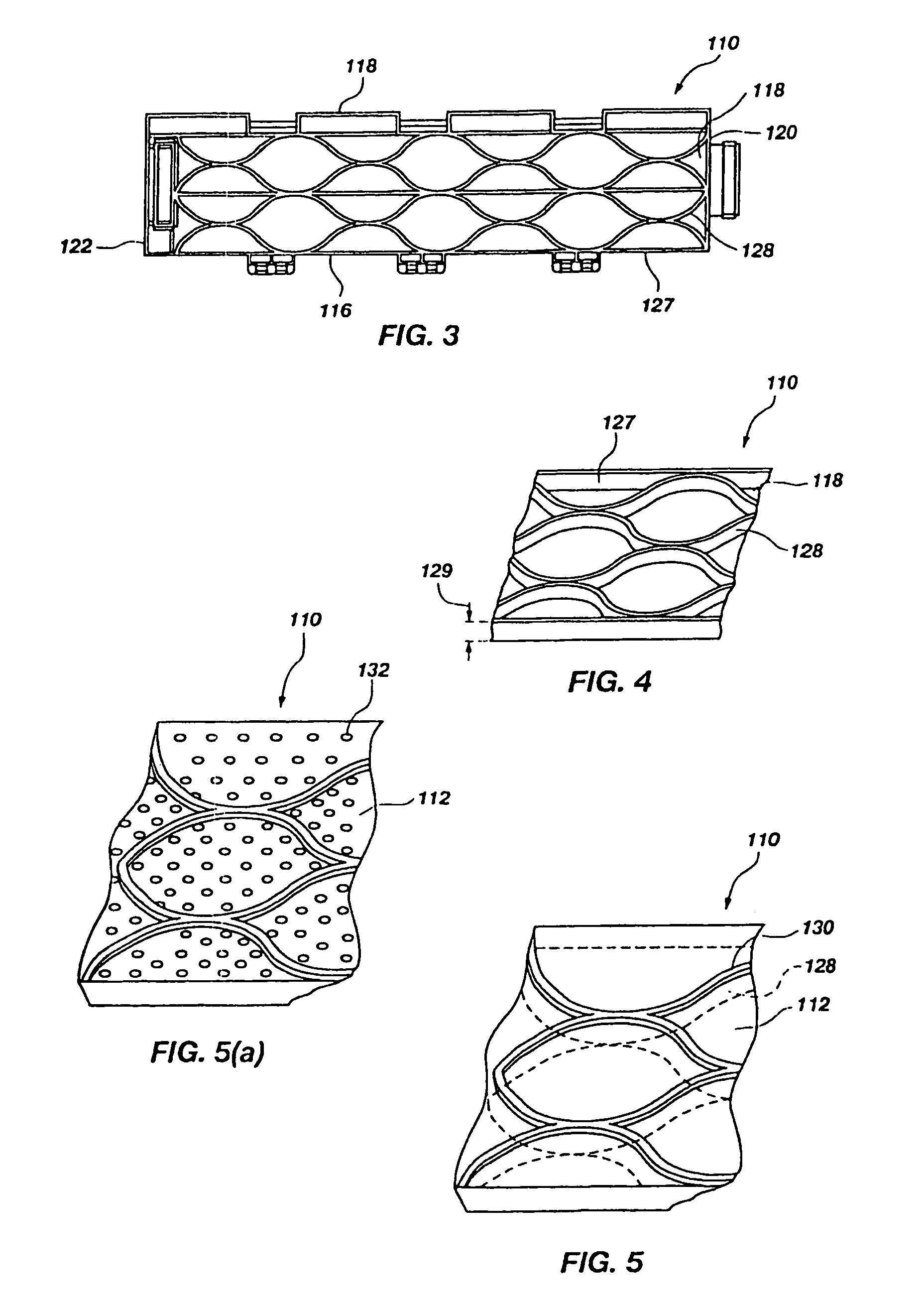
[0033]The following detailed description of exemplary embodiments of the invention makes reference to the accompanying drawings, which form a part hereof and in which are shown, by way of illustration, exemplary embodiments in which the invention may be practiced. While these exemplary embodiments are described in sufficient detail to enable those skilled in the art practice the invention, it should be understood that other embodiments may be realized and that various changes to the invention may be made without departing from the spirit and scope of the present invention. Thus, the following more detailed description of the embodiments of the present invention, as represented in FIGS. 1 through 13, is not intended to limit the scope of the invention, as claimed, but is presented for purposes of illustration only and not limitation to describe the features and characteristics of the present invention, to set forth the best mode of operation of the invention, and to sufficiently enab...


PUM

PropertyMeasurementUnit
lengthaaaaaaaaaa
longitudinal lengthaaaaaaaaaa
coupling lengthaaaaaaaaaa

Abstract

A method and apparatus providing a tile configured to form a modular floor covering including an array of substantially identical tiles. The tile includes a top surface, bottom side, front and rear sides and first and second lateral sides. The top surface includes an elongated shape and the bottom side includes a support grid. The front and rear sides are defined along a longitudinal length of the elongated shape. The front side includes at least one first hinge member and the rear side includes at least one complementary second hinge member configured to be engageable with the at least one first hinge member of an adjacently positioned tile. The first and second lateral sides define a width of the elongated shape with the first and second lateral sides including a respective tab and slot coupling portion each having a coupling length at least one-third the width of the elongated shape.

Description

RELATED APPLICATIONS[0001]This application claims priority to U.S. Provisional Application Ser. No. 60 / 552,952, filed Mar. 12, 2004, which is incorporated by reference herein in its entirety.FIELD OF THE INVENTION[0002]The present invention relates generally to tiles for a synthetic modular floor covering. More particularly, the present invention relates to a coupling configuration for coupling the tiles to form the modular floor covering.BACKGROUND OF THE INVENTION AND RELATED ART[0003]Numerous types of flooring have been used to create playing areas for such sports as basketball and tennis, as well as for other purposes. These flooring assemblies include concrete, asphalt, wood and other materials which have varying characteristics. For each type of flooring, there are corresponding advantages and disadvantages. For example, concrete flooring is easy to construct and provides long term wear. However, the concrete provides no “give” during use and many people are injured each year ...

Claims


Application Information

Patent Timeline
Patent Type & Authority Patents(United States)
IPC IPC(8): E04F11/16E01C5/20E01C9/08E04B2/00E04F13/08E04F15/10
CPCE01C5/20E01C9/086E04F15/10E01C2201/12E04F2201/0138E04F2201/0153E04F2201/0594E04F2201/091E04F2201/096E04F15/16
Inventor FORSTER, CHERYLJENKINS, MARKLAITINEN, TYLER
Owner CONNOR SPORT COURT INT
Learn More