Multifunctional cover device with a detachable PDA device
a multi-functional, pda technology, applied in the field of multi-functional cover devices, can solve the problems of inconvenient carrying of huge bags to work or school, inconvenient simultaneous carrying of notepads and personal micro computers, and inconvenient carrying of large bags, etc., to achieve convenient use, increase the capability of information storage, and simple structure
- Summary
- Abstract
- Description
- Claims
- Application Information
AI Technical Summary
Benefits of technology
Problems solved by technology
Method used
Image
Examples
embodiment 1
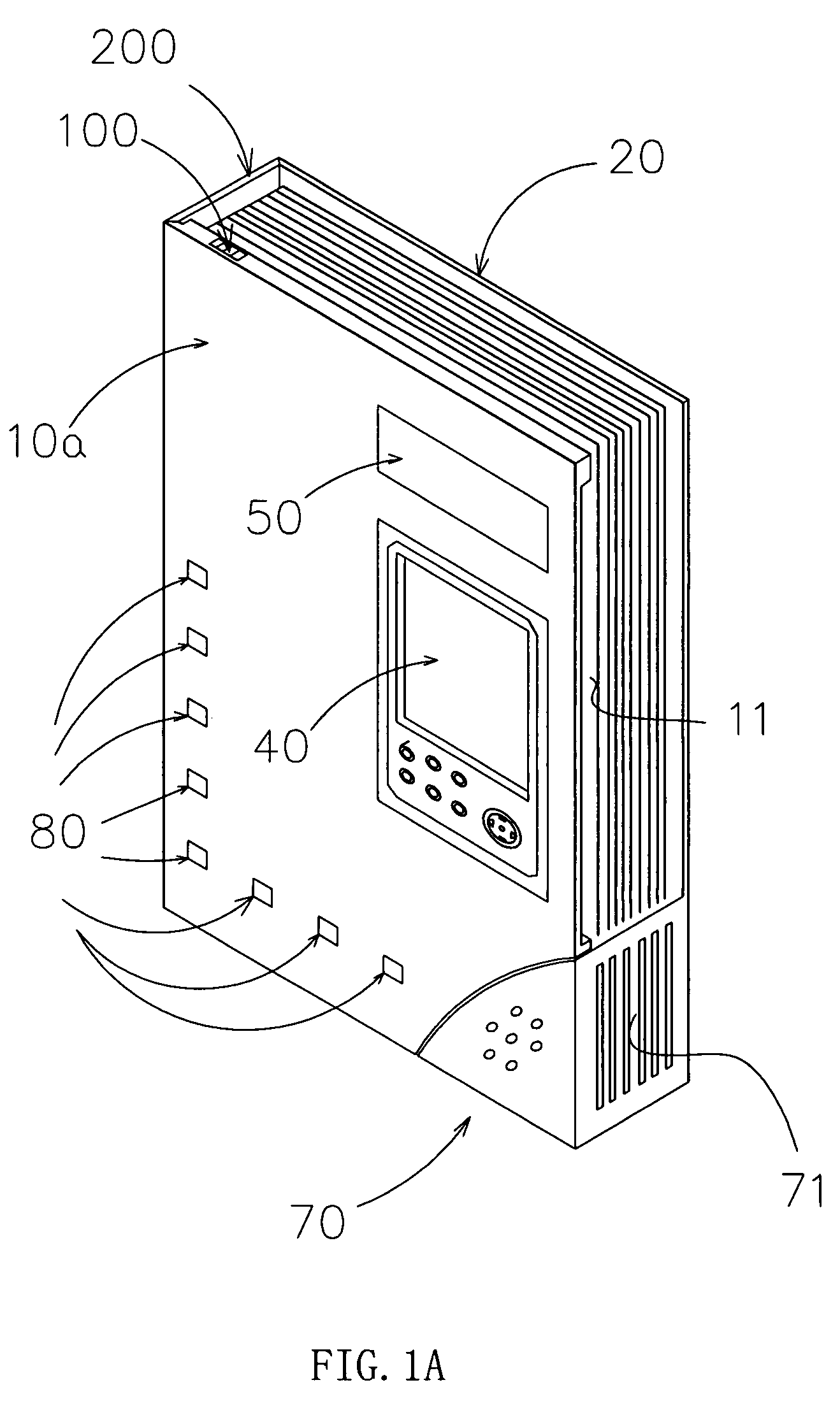
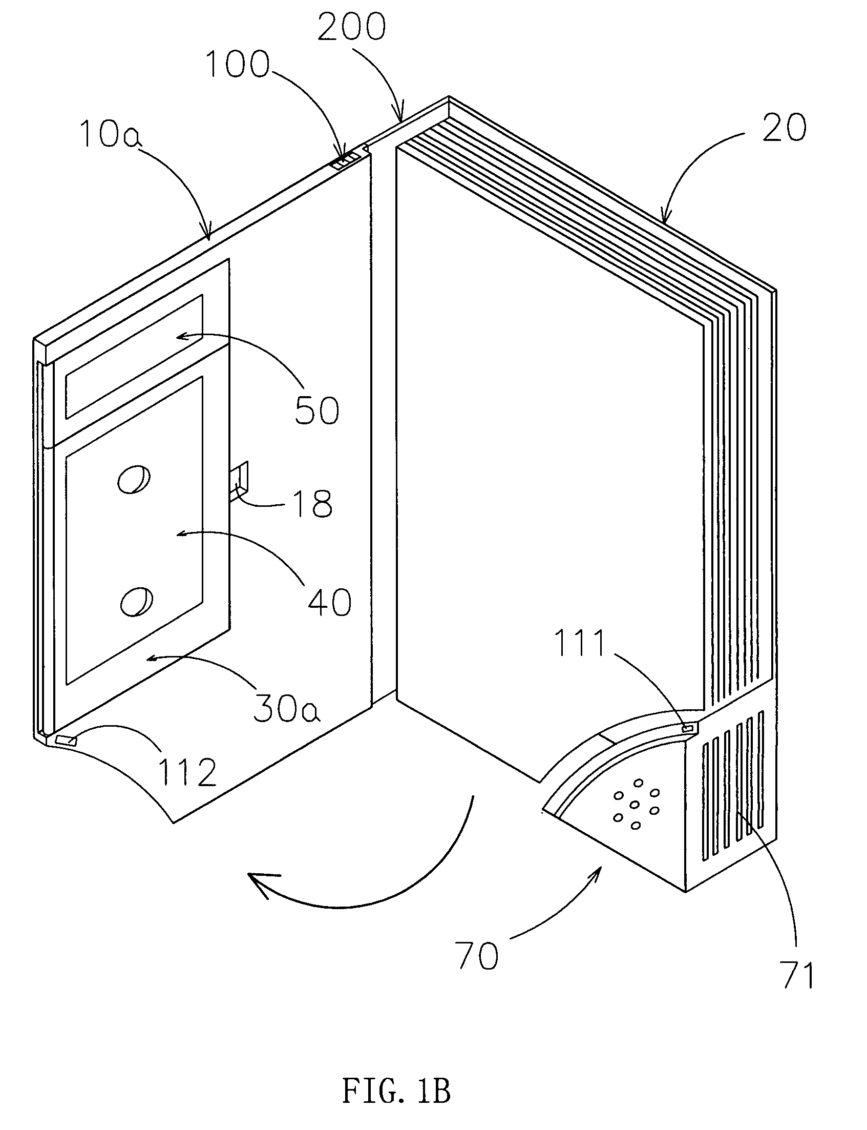
[0023]A multifunctional cover device for PDA with a rotatable accessory panel is illustrated in this embodiment. Referring to FIG. 1 and FIG. 2, the cover device comprises a front cover 10a and a back cover 20, which are connected by connecting edge panel 200. Unlike traditional covers, front cover 10a, back cover 20 and connecting edge panel 200 are hollow slabs made by injection molding process. A concave surface 11 is located at the interior side of the front cover 10a. There is at least one rotatable accessory panel 30a foldably mounted on the concave surface 11 and the thickness of the rotatable accessory panel 30a is the same as the depth of the concave surface of the front cover 10a. A hinge through hole is formed at each of the top and bottom edge of the accessory panel 30a to pivotally connect the accessory panel 30a on the front cover 10a through a hinge axle 31, as shown in FIG. 2A. The cables are extended through the hinge through hole to operatively connect to PDA devic...
embodiment 2
[0024]Referring to FIGS. 3A and 3B, the basic structure of the present embodiment is identical to the embodiment 1 and the only difference is that the rotatable accessory panel 30a is located at external side of the front cover 10a.
embodiment 3
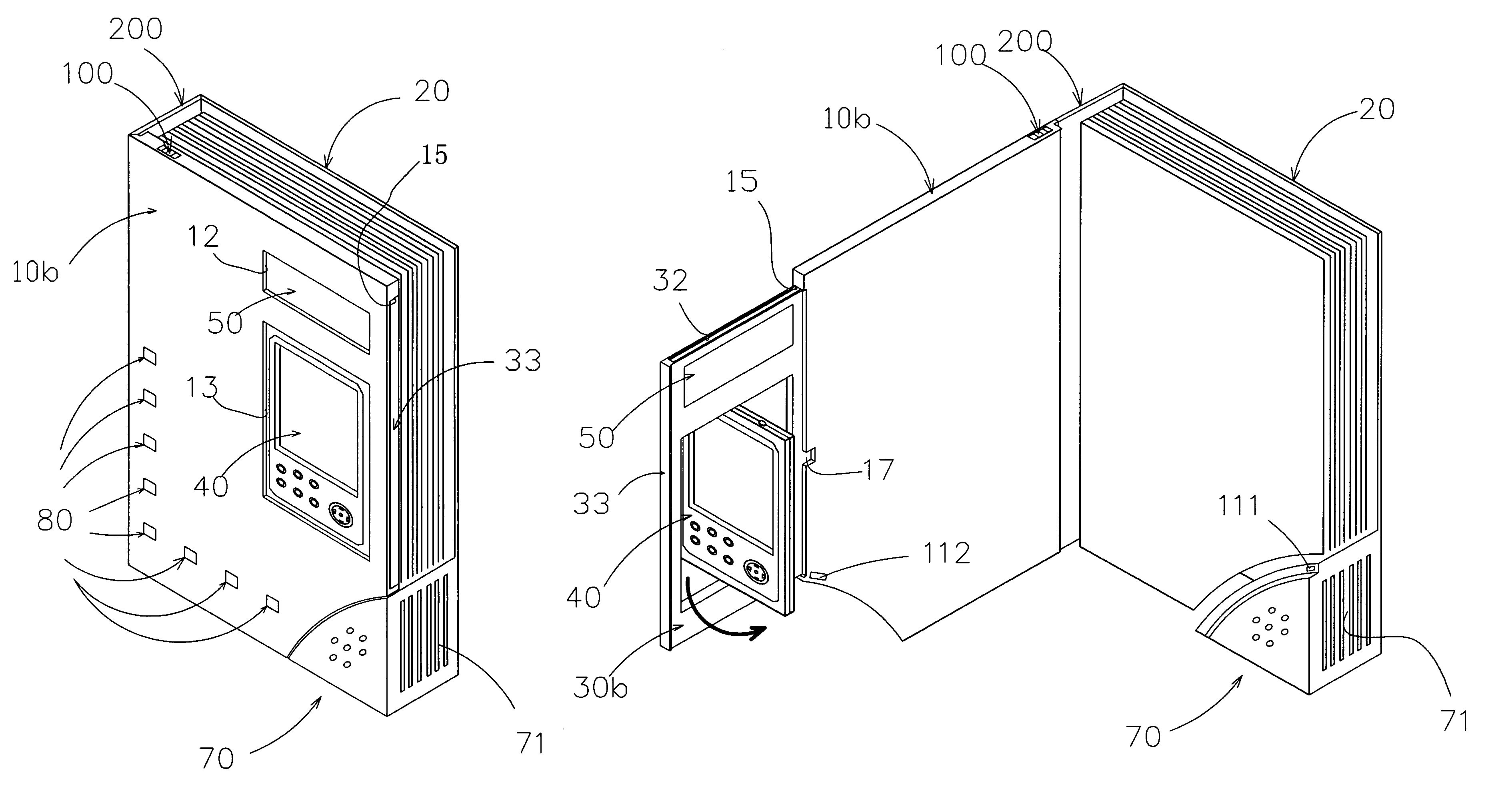
[0025]In this embodiment, a multifunctional cover device for PDAs with an accessory panel which can be pushed-in and pulled-out is illustrated. The basic structure of the present embodiment is identical to the embodiment 1 and the only difference is that the accessory panel can be pushed-in and pulled-out. As shown in FIG. 4, the push-and-pull accessory panel 30b is located at the push-and-pull cavity inside the front cover 10b. The structure of the pull-and-push accessory panel is shown in FIG. 5A, wherein an accessory panel opening 15 is located at one side or a plurality of sides of the front cover 10b, and the accessory panel 30b can be pulled out, and thus forms an extendable front cover board, as shown in FIGS. 4B to 4E and 5D) and the accessory panel can be restored to the front cover 10b, as shown in FIGS. 4A and 5C. As shown in FIG. 5B, two position columns 16 with through holes are each placed at the upper and lower lateral wall in the inner chamber of the front cover 10b....
PUM
 Abstract
Description
Claims
Application Information
 - R&D
- Intellectual Property
- Life Sciences
- Materials
- Tech Scout
- Unparalleled Data Quality
- Higher Quality Content
- 60% Fewer Hallucinations
Browse by: Latest US Patents, China's latest patents, Technical Efficacy Thesaurus, Application Domain, Technology Topic, Popular Technical Reports.
© 2025 PatSnap. All rights reserved.Legal|Privacy policy|Modern Slavery Act Transparency Statement|Sitemap|About US| Contact US: help@patsnap.com


