Oscillator device, optical deflector and optical instrument using the same
a technology of oscillator and deflector, which is applied in the direction of instruments, mountings, springs/dampers, etc., can solve the problem of dispersion of the frequency (resonance frequency) of the natural oscillation mod
- Summary
- Abstract
- Description
- Claims
- Application Information
AI Technical Summary
Benefits of technology
Problems solved by technology
Method used
Image
Examples
first embodiment
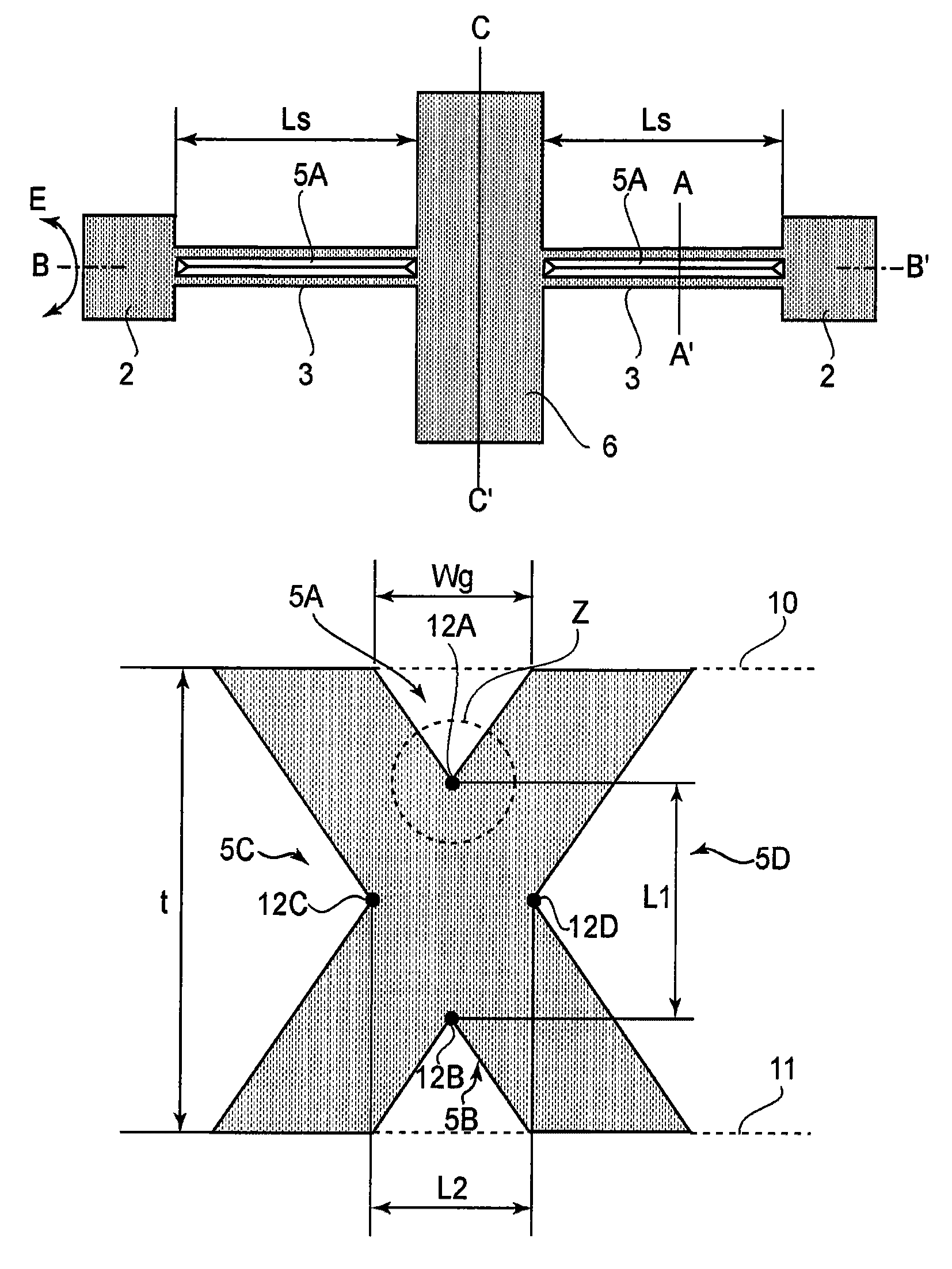
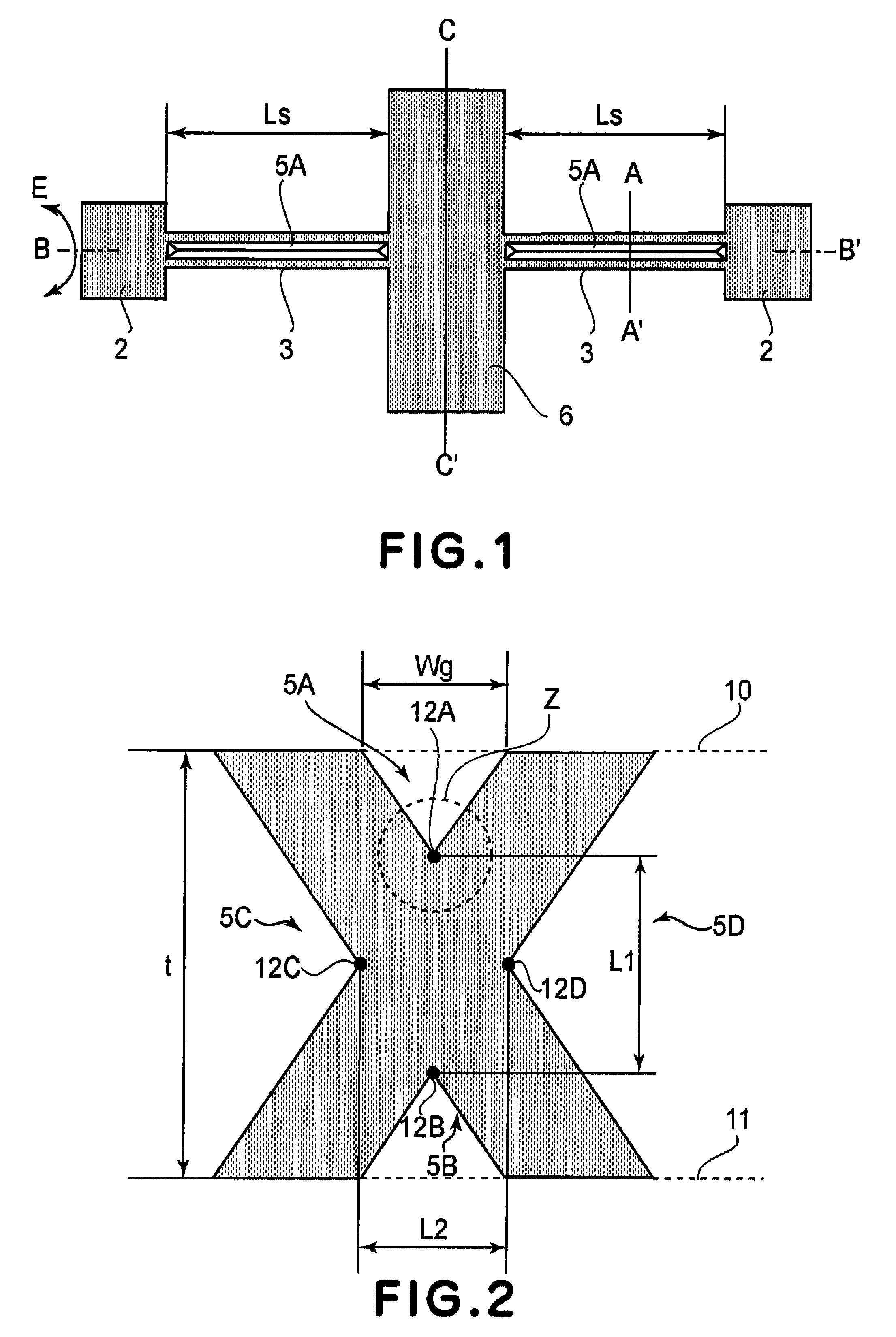
[0035]The present invention in an aspect thereof concerns an oscillator device which includes a movable member, a torsion spring and a supporting base plate, wherein the movable member is supported by the torsion spring for torsional oscillation about a torsion axis, relative to the supporting substrate.
[0036]Conventionally, in order to set the resonance frequency of an oscillator device at a predetermined resonance frequency, the inertia moment of the movable member and the spring constant of the torsion spring are used as design values. This is because the resonance frequency of the oscillator device is determined in accordance with the inertia moment of the movable member and the spring constant of the torsion spring.
[0037]However, silicon wafers which are the materials for making oscillator devices may have a thickness error which will lead to an error in the inertia moment of the movable member and the spring constant of the torsion spring and cause an error in the resonance fr...
second embodiment
[0080]FIG. 11A and FIG. 11B are diagrams showing an oscillator device according to a second embodiment of the present invention.
[0081]FIG. 11A is a top plan view of the oscillator device, and FIG. 11B is a sectional view taken on a line D-D′. In FIGS. 11A and 11B, components corresponding to those of FIG. 1 are denoted by like numerals. As shown in FIG. 11A, in the oscillator device of the second embodiment, a first movable member 8 is supported by a first torsion spring 15, for torsional oscillation relative to a supporting base plate 2 about a torsion axis B. Then, the second movable member 9 is supported by a second torsion spring 16, for torsional oscillation relative to the first movable member 8 about the torsion axis B. Here, the first movable member 8, first torsion spring 15, second movable member 9 and second torsion spring 16 are referred to as a movable system.
[0082]As described above, the movable system of the oscillator device of the second embodiment constitutes a two...
third embodiment
[0105]FIG. 13 is a perspective view showing an embodiment of an optical instrument using an optical deflector according to the present invention.
[0106]Here, an image forming apparatus is shown as the optical instrument. In FIG. 13, denoted at 3003 is an optical deflector of the present invention which is arranged, in the present embodiment, to scanningly deflect an incident light beam. Denoted at 3001 is a laser source. Denoted at 3002 is a lens or lens group. Denoted at 3004 is a writing lens or lens group. Denoted at 3005 is a photosensitive member.
[0107]The laser beam projected from the laser source 3001 undergoes predetermined intensity modulation related to the timing of the scanning deflection of the light. The intensity-modulated light goes through the lens or lens group 3002 and then it is scanningly deflected by the optical scanning system (optical deflector) 3003. By the function of the writing lens or lens group 3004, the thus scanned laser beam forms an image (electrosta...
PUM
 Abstract
Description
Claims
Application Information
 - R&D
- Intellectual Property
- Life Sciences
- Materials
- Tech Scout
- Unparalleled Data Quality
- Higher Quality Content
- 60% Fewer Hallucinations
Browse by: Latest US Patents, China's latest patents, Technical Efficacy Thesaurus, Application Domain, Technology Topic, Popular Technical Reports.
© 2025 PatSnap. All rights reserved.Legal|Privacy policy|Modern Slavery Act Transparency Statement|Sitemap|About US| Contact US: help@patsnap.com


