Optical displacement measurement device

A technology for measuring displacement and optics, which is applied in the direction of using optical devices, measuring devices, instruments, etc., can solve the problems of poor frequency stability and low precision of displacement measurement, and achieve the effects of good frequency stability, easy adjustment, and elimination of measurement errors

Inactive Publication Date: 2013-06-19
UNIV OF SHANGHAI FOR SCI & TECH
View PDF4 Cites 3 Cited by
  • Summary
  • Abstract
  • Description
  • Claims
  • Application Information

AI Technical Summary

Problems solved by technology

However, the frequency stability of the above-mentioned displacement measuring instrument is poor, resulting in low precision of displacement measurement

Method used


Image

  • Optical displacement measurement device
  • Optical displacement measurement device
  • Optical displacement measurement device

Examples


Embodiment 1

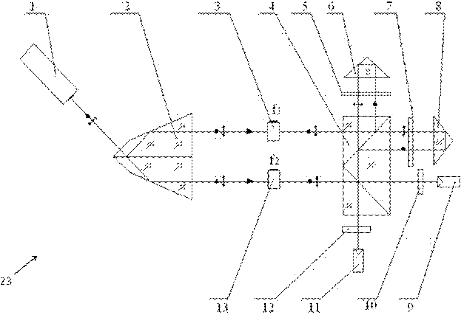
[0031] figure 1 It is a schematic structural diagram of an optical displacement measuring device according to an embodiment of the present invention.

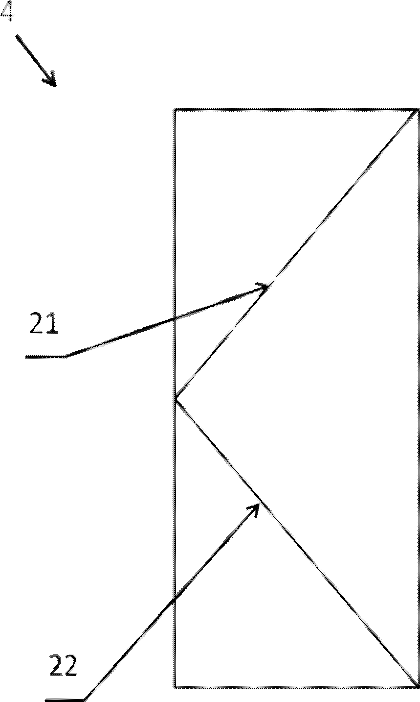
[0032] Such as figure 1 As shown, the optical displacement measuring device 23 includes a light source 1, a seven-sided dichroic prism 2, a first light modulator 3, a second light modulator 13, a polarization beam splitter 4, a first quarter wave plate 5, a second four A quarter-wave plate 7 , a first corner cube prism 6 , a second corner cube prism 8 , a first polarizer 10 , a second polarizer 12 , a first light receiver 9 and a second light receiver 11 .

[0033] Wherein, the light source 1 is a He-Ne laser, which is used to emit laser light, the laser light is circularly polarized light, and the frequency is f.

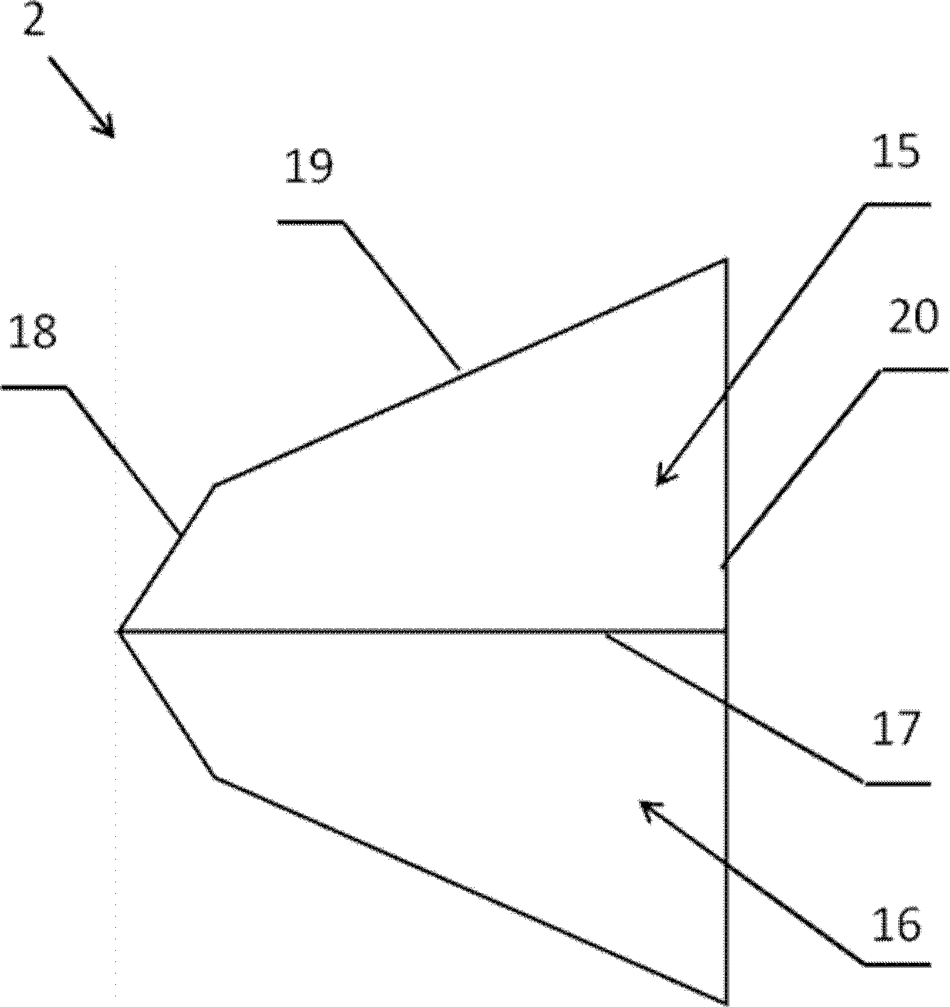
[0034] figure 2 It is a structural schematic diagram of a seven-sided beam splitting prism in an embodiment of the present invention.

[0035] Such as figure 2 As shown, the seven-sided dichroic prism 2 has a...

Embodiment 2

[0096] In the optical displacement measuring device, the laser light emitted by the light source may also be linearly polarized light whose polarization direction is 45° to the horizontal axis. The frequency difference between the first outgoing light modulated by the first light modulator and the second outgoing light modulated by the second light modulator may also be 100 MHz. The first corner cube prism can also be arranged on the measured object, above the first quarter-wave plate. The first corner cube is fixedly placed. Other devices of embodiment two are identical with embodiment one.

[0097] Because the first corner cube is set on the measured object and above the first quarter-wave plate, the first signal is used as the reference signal, the second signal is used as the measurement signal, and the displacement calculation formula of the measured object is the same as the implementation example one.


PUM


Abstract

The invention discloses an optical displacement measurement device based on light modulation. The device comprises a light source, a heptahedron light splitting prism, two light modulators, a polarization light-splitting mirror, two quarter-wave plates, two polarization sheets and two corresponding light receivers. According to the device, two light beams which are generated by the heptahedron light splitting prism and have the identical frequency are subjected to frequency modulation by using the two light modulators to obtain two light beams with different frequencies, and the order of magnitude of frequency difference is MHz. The device is small in non-linear error, and the two light beams with different frequencies are not required to be combined, so that an optical system is simple, a light path is easily regulated, and the reliability is high; and the device can be applied to high speed measurement and has a relatively high practical value and economic value.

Description

technical field [0001] The invention relates to an optical displacement measuring device. Background technique [0002] The heterodyne interferometer can achieve high measurement resolution by simple phase comparison. Due to its simple structure and strong anti-interference ability, it is widely used in the field of nanometer measurement technology. The development of the manufacturing industry urgently requires the measurement and positioning of objects during high-speed processing, and high-speed measurement requires high-frequency differences. [0003] Some dual-frequency laser interferometers at home and abroad mostly use the Zeeman effect to generate dual frequencies. The measurement accuracy of the dual-frequency laser interferometer based on the Zeeman effect is limited by the nonlinear error of the optical system itself, and the frequency difference Small, the maximum frequency difference generally does not exceed 4MHz, and the measurement speed cannot be too high. ...

Claims


Application Information

Patent Timeline
Patent Type & Authority Applications(China)
IPC IPC(8): G01B11/02
Inventor 句爱松肖凯敏钟朝阳刘丹玥
Owner UNIV OF SHANGHAI FOR SCI & TECH
Why Eureka
Try Eureka