
Safe gear box for electrical steering column lock

Inactive Publication Date: 2010-12-28
U SHIN DEUT ZUGANGSSYST
View PDF17 Cites 23 Cited by
  • Summary
  • Abstract
  • Description
  • Claims
  • Application Information

AI Technical Summary

Benefits of technology

[0004]The invention is based on the object of indicating a steering lock of the type mentioned at the beginning, in which the blocking element is securable in its unlocking position in a simple manner by a securing element even when the electromechanical drive bringing about the displacement of the blocking element is a worm drive.

Problems solved by technology

Due to the large distance between the control contour and the blocking element, a space-consuming lever device is required for this known steering lock.
A securing of the blocking bolt in its unlocking position is not envisaged, and therefore, for example if the worm wheel is damaged, a situation which is questionable in terms of safety may occur (displacement of the blocking element into the locking position during a journey).

Method used


Image

  • Safe gear box for electrical steering column lock
  • Safe gear box for electrical steering column lock
  • Safe gear box for electrical steering column lock

Examples


Embodiment Construction

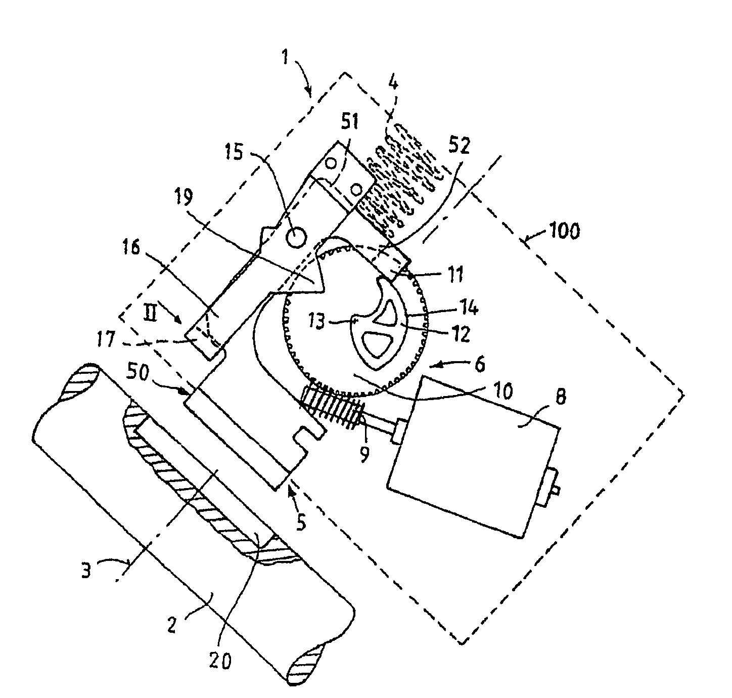
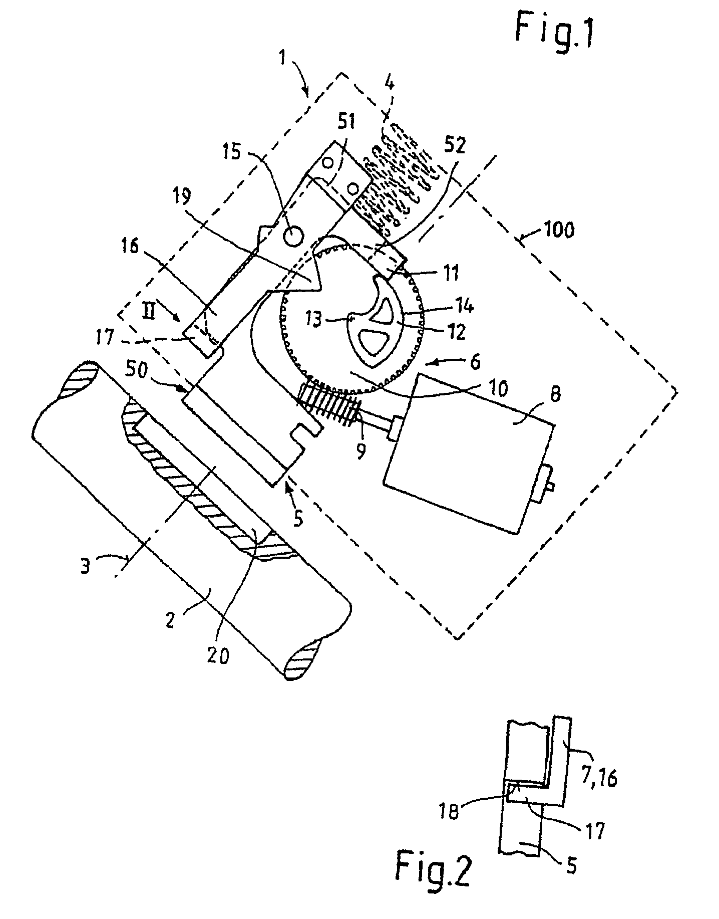
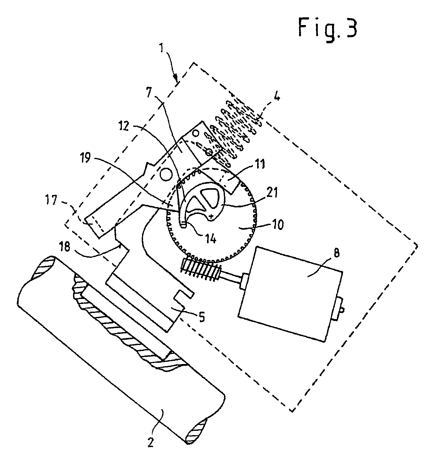
[0016]In FIG. 1, 1 denotes a steering lock according to the invention for locking a steering spindle 2 of a motor vehicle. The steering lock 1 comprises a housing 100 (only indicated by dashed lines) and a blocking element 5 which is displaceable in the direction of its longitudinal axis 3 by means of a spring 4, is actuable from a locking position into an unlocking position by means of an electromechanical worm drive 6 and is securable in the unlocking position by means of a spring-actuated securing element 7 in the form of a lever.

[0017]The worm drive 6 essentially comprises an electric motor 8, on the output shaft of which there is a worm 9 which, for its part, engages in the teeth of a worm wheel 10 which is situated in a starting position.

[0018]The blocking element 5 comprises a bolt-shaped lower part 50 and a bow-shaped upper part 51 adjoining the lower part 50, with at least a partial region of that arm 52 of the upper part 51 which lies opposite the bolt-shaped lower part 50...


PUM


Abstract

A steering lock for locking the steering spindle of a motor vehicle steering system including a blocking element that pivots along a longitudinal axis from a locking to an unlocking position using an electromechanical drive and is maintained in the unlocking position by a spring-loaded lever. In order to enable the lever to maintain the blocking element in the unlocking position when a worm drive generates the displacement of the blocking element, a worm gear representing a first control contour is used. A first cam for pivoting the blocking element to the unlocking position and a second cam for actuating the lever are mounted on the worm gear. Prior to the pivoting of the blocking element from the unlocking to the locking position, the lever is pivoted from a rest into a release position and, only afterwards, the worm gear enables the blocking element to pivot to the locking position.

Description

FIELD OF THE INVENTION[0001]The invention relates to a steering lock for locking the steering spindle of a motor vehicle steering system.BACKGROUND OF THE INVENTION[0002]A steering lock of this type is known, for example, from DE 199 64 173 C2. In this case, the steering lock comprises a blocking element which is displaceable in the direction of its longitudinal axis, is actuable from the locking position into an unlocking position by means of an electromechanical drive and is securable in the unlocking position by a securing element. The electromechanical drive is a spindle drive. The activation of the securing element in order to release the blocking element, when the latter is to be displaced from its unlocking position into its locking position, takes place by means of a control cam which is supported on a control contour of the threaded spindle, said control contour being situated on that side of the threaded spindle, which faces away from the blocking element. Due to the large...

Claims


Application Information

Patent Timeline
IPC IPC(8): B60R25/02B60R25/021B60R25/0215
CPCB60R25/02142B60R25/02153Y10T70/7028Y10T70/5664B60R25/021B60R25/022B60R25/04B60R25/10
Inventor LAVAL, ANTHONYSTARKEN, HARALD
Owner U SHIN DEUT ZUGANGSSYST
Features
  • Generate Ideas
  • Intellectual Property
  • Life Sciences
  • Materials
  • Tech Scout
  • Unparalleled Data Quality
  • Higher Quality Content
  • 60% Fewer Hallucinations
Learn More