Method of and power plant for generating power by oxyfuel combustion

a technology of oxyfuel combustion and power generation process, which is applied in the direction of greenhouse gas reduction, separation processes, lighting and heating apparatus, etc., can solve the problems of increasing the total production cost of the power generation process, and reducing the net power produced, so as to reduce the cost or loss of produced power due to carbon dioxide removal

Inactive Publication Date: 2011-01-25
AMEC FOSTER WHEELER POWER EQUIP CO INC
View PDF21 Cites 102 Cited by
  • Summary
  • Abstract
  • Description
  • Claims
  • Application Information

AI Technical Summary

Benefits of technology

[0011]An object of the present invention is to provide a method of and a power plant for oxyfuel combustion, wherein the costs or losses of produced power due to carbon dioxide removal are minimized.

Problems solved by technology

Oxyfuel combustion is more complicated than conventional combustion because of the need of an oxygen supply, typically, a cryogenic air separation unit (ASU), where air is cooled and compressed so that oxygen can be separated from other components of air, mainly, nitrogen.
Both the production of oxygen and the compression / purification of carbon dioxide increase the total production costs of the power generation process, for example, by decreasing the net power produced in the process.

Method used


Image

  • Method of and power plant for generating power by oxyfuel combustion
  • Method of and power plant for generating power by oxyfuel combustion

Examples


Embodiment Construction

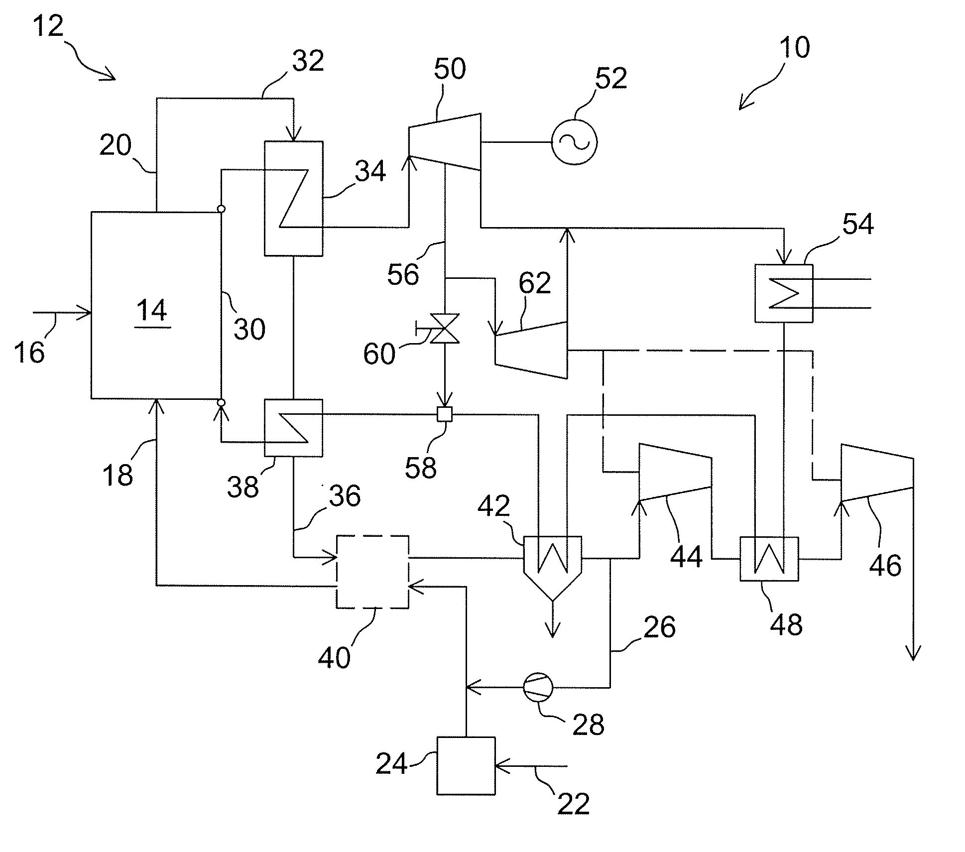
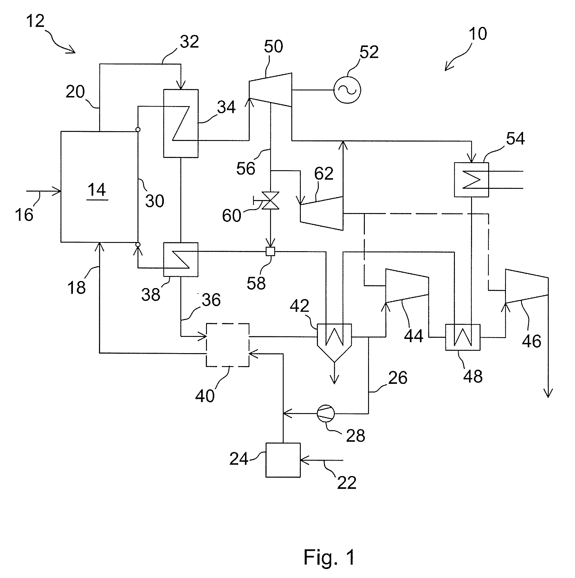
[0034]FIG. 1 shows a schematic diagram of a power plant 10 in accordance with a preferred embodiment of the present invention. The power plant 10 comprises a boiler 12, which may be for, for example, a pulverized coal (PC) boiler or a circulating fluidized bed (CFB) boiler. The furnace 14 of the boiler comprises conventional fuel feeding means 16, means for introducing oxygen-containing inlet gas 18 into the furnace, and an exhaust gas channel 20 for discharging exhaust gas produced by combusting the fuel with the oxygen of the inlet gas. The details and type of some elements of the boiler 12, such as the fuel feeding means 16 and inlet gas feeding means 18, depend naturally on the type of the boiler. Such details, for example, burners, coal mills, means for feeding separately primary and secondary inlet gas, are, however, not important for the present invention, and they are thus not shown in FIG. 1.

[0035]The oxygen-containing inlet gas is preferably a mixture of substantially pure...


PUM


Abstract

A method of and a power plant for generating power by combusting carbonaceous fuel with substantially pure oxygen, and a method of modifying a process of generating power by combusting carbonaceous fuel from combusting the fuel with air to combusting the fuel with substantially pure oxygen. The methods include feeding substantially pure oxygen into a furnace for combusting fuel with the oxygen to produce exhaust gas including mainly carbon dioxide and water, recovering low-grade heat from the exhaust gas by using multiple exhaust gas coolers arranged in a downstream portion of the exhaust gas channel, wherein a first portion of the recovered low-grade heat is used for preheating feedwater; pressurizing a first portion of the exhaust gas in multiple exhaust gas compressors so as to produce liquid carbon dioxide, recycling a second portion of the exhaust gas to the furnace via an exhaust gas recycling channel, using a first portion of steam extracted from a steam turbine system to preheat feedwater, wherein the first portion of the recovered low-grade heat is more than 50% of the total amount of recovered low-grade heat, or larger than the first portion of the recovered low-grade heat in the air-fired process, allowing minimizing of the first portion of the extracted steam, and the expanding of a second portion of the extracted steam in at least one auxiliary steam turbine for driving at least one compressor or at least one pump of the power plant.

Description

BACKGROUND OF THE INVENTION[0001]1. Field of the Invention[0002]The present invention relates to a method of and a power plant for efficient oxyfuel combustion, and to a method of modifying a process of generating power by combusting carbonaceous fuel from combusting the fuel with air to combusting the fuel with substantially pure oxygen. More particularly, the present invention relates to oxyfuel combustion including carbon dioxide removal, wherein the costs or losses of produced power due to the carbon dioxide removal are minimized.[0003]2. Description of the Related Art[0004]Oxyfuel combustion is one of the methods suggested for removing CO2 from the combustion gases of a power generating boiler, such as a pulverized coal (PC) boiler or circulating fluidized bed (CFB) boiler. Oxyfuel combustion is based on combusting carbonaceous fuel with substantially pure oxygen, typically of about 95% purity, so as to have carbon dioxide and water as the main components of the exhaust gas dis...

Claims


Application Information

Patent Timeline
Patent Type & Authority Patents(United States)
IPC IPC(8): F02C7/10F02G1/00
CPCB01D53/002F01K7/16F23J15/06F23L7/007F23N3/002B01D53/62Y02E20/363B01D2257/504F23J2900/15061F23L2900/07001F23L2900/07003Y02C10/04Y02E20/322Y02E20/328Y02E20/344Y02A50/20Y02C20/40Y02E20/32Y02E20/34Y02E20/30
Inventor FAN, ZHENSELTZER, ANDREWHACK, HORST
Owner AMEC FOSTER WHEELER POWER EQUIP CO INC
Why Eureka
Try Eureka