Charging circuit for an energy storage device, and method for charging an energy storage device

a charging circuit and energy storage technology, applied in circuit monitoring/indication, electric vehicles, transportation and packaging, etc., can solve the problems of increased complexity, increased installation space and material usage, and the control region of the resonant inductive transmission path may not be sufficient, so as to reduce the fluctuations of voltage

Inactive Publication Date: 2014-08-21
ROBERT BOSCH GMBH
View PDF7 Cites 5 Cited by
  • Summary
  • Abstract
  • Description
  • Claims
  • Application Information

AI Technical Summary

Benefits of technology

[0017]According to a further embodiment of the charging circuit according to the invention, the charging circuit can have a DC voltage intermediate circuit which is coupled between the output connections of the energy storage device. This advantageously makes it possible to reduce fluctuations in voltage or current in the output voltage or in the input current of the energy storage device in the charging mode, in particular when one or more of the energy storage modules are actuated in a pulse-width-modulated manner.
[0018]According to one embodiment of the method according to the invention, actuating the coupling devices of the energy storage modules can comprise selectively connecting or disconnecting the energy storage cell modules into/from the respective energy supply section. Furthermore, the method can further exhibit the step of cyclically exchanging the energy storage cell mod

Problems solved by technology

Specifically in the region of high end-of-charge voltages, that is to say shortly before the full state of charge is reached, battery modules can only handle a reduced power supply without suffering damage.
The possi

Method used


Image

  • Charging circuit for an energy storage device, and method for charging an energy storage device
  • Charging circuit for an energy storage device, and method for charging an energy storage device
  • Charging circuit for an energy storage device, and method for charging an energy storage device

Examples


Embodiment Construction

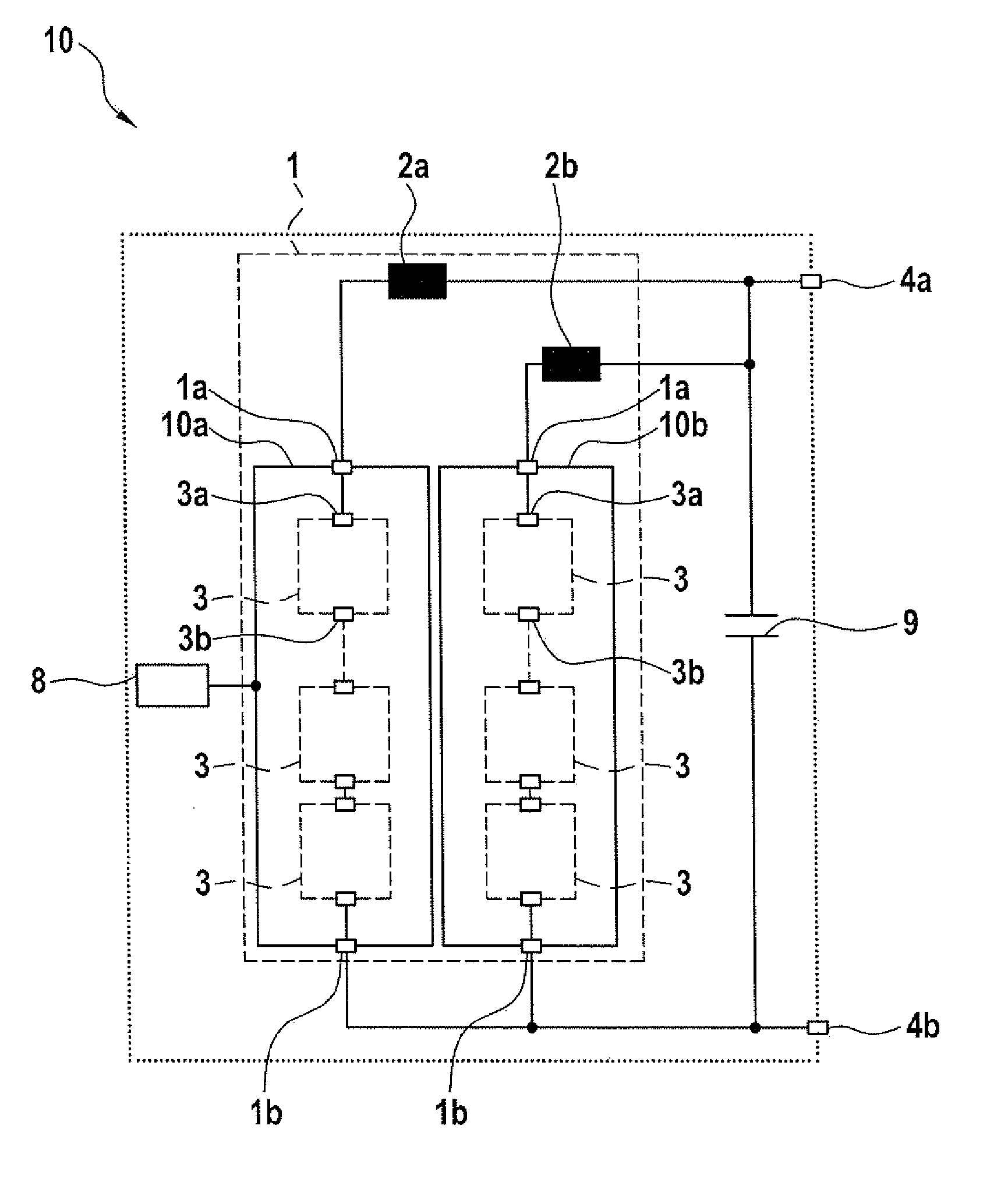
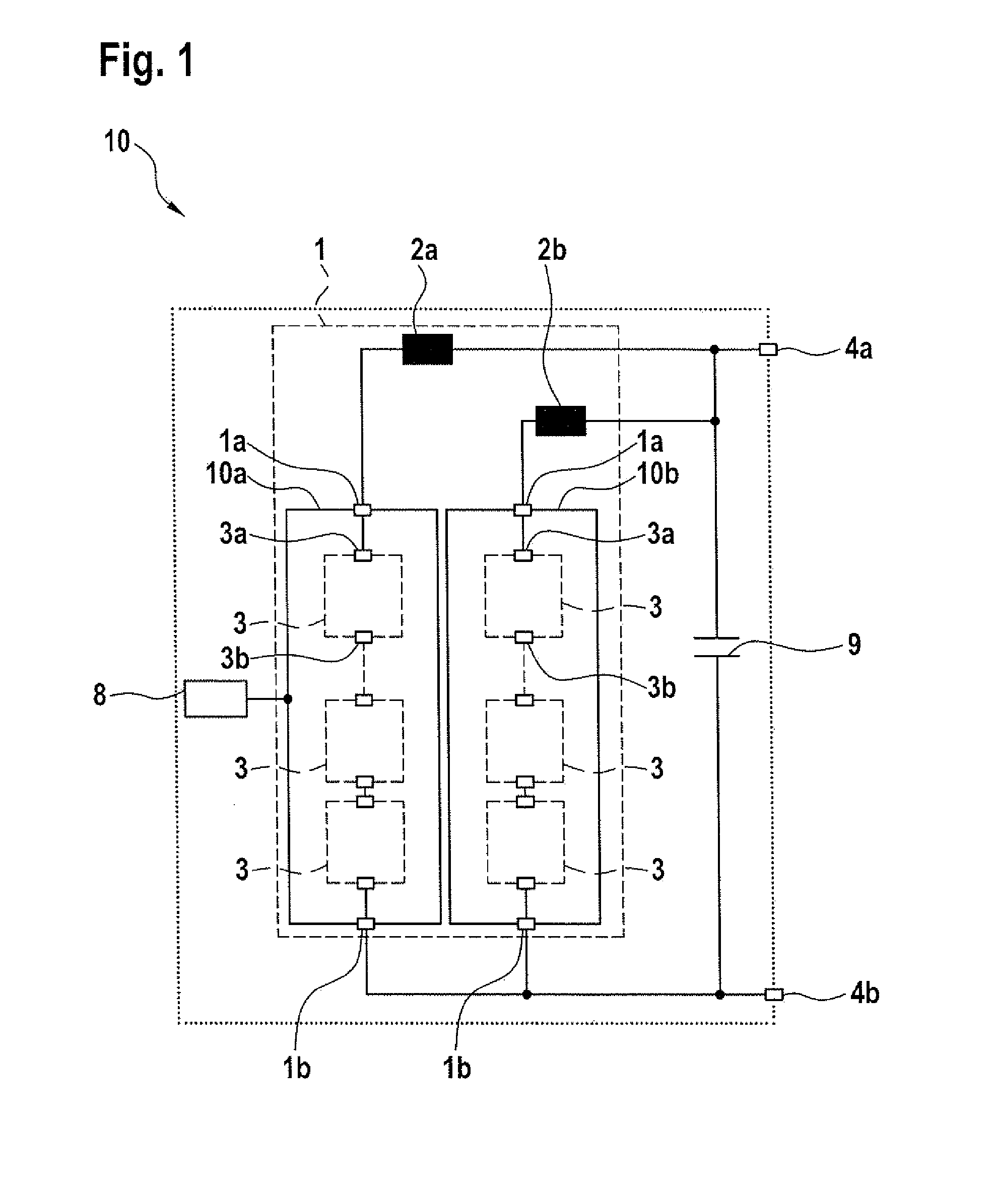
[0029]FIG. 1 shows an energy storage device 10 having a battery module 1 for providing a supply voltage by energy supply sections 10a, 10b, which can be connected in parallel, between two output connections 4a and 4b of the energy storage device 10. The energy supply sections 10a, 10b each have section connections 1a and 1b. The energy storage device 10 has at least two energy supply sections 10a, 10b which are connected in parallel. The number of energy supply sections 10a, 10b in FIG. 1 is, by way of example, two, but any other larger number of energy supply sections 10a, 10b is likewise possible. In this case, it is equally also possible to connect only one energy supply section 10a between the section connections 1a and 1b, said section connections forming the output connections 4a, 4b of the energy storage device 10 in this case.

[0030]In this case, the energy supply sections 10a, 10b can be coupled to the output connection 4a of the energy storage device 10 by means of storage ...


PUM


Abstract

A charging circuit for an energy storage device having an inductive transmitter element designed to inductively receive a charging AC voltage. In one embodiment, a rectifier is coupled to the inductive transmitter element and designed to convert the received charging AC voltage into a charging DC voltage. The energy storage device has at least one energy supply section coupled between two output connections of the energy storage device. The energy supply section has one or more energy storage modules connected in series in the power supply section. The energy storage modules each have an energy storage cell module having at least one energy storage cell, and a coupling device having a large number of coupling elements.

Description

BACKGROUND OF THE INVENTION[0001]The invention relates to a charging circuit for an energy storage device, and to a method for charging an energy storage device, in particular for charging battery direct converter circuits and battery converter circuits which are used, for example, in electrical drive systems of electrically operated vehicles.[0002]The trend is that in the future electronic systems which combine new energy storage technologies with electrical drive technology will be increasingly used both in stationary applications, such as wind power installations or solar installations, and in vehicles, such as hybrid or electric vehicles.[0003]A DC voltage, which is provided by a DC voltage intermediate circuit, is usually converted into a three-phase AC voltage by means of a converter in the form of a pulse-controlled inverter for the purpose of feeding three-phase alternating current to an electric machine. The DC voltage intermediate circuit is fed by a line of battery module...

Claims


Application Information

Patent Timeline
IPC IPC(8): H02J7/02
CPCH02J7/025H02J7/0048H02J50/10H02J50/12H02J7/02H02J7/00
Inventor FEUERSTACK, PETER
Owner ROBERT BOSCH GMBH
Why Eureka
Try Eureka