Lubrication scavenge system

a lubricant and scavenging technology, applied in the direction of blade accessories, turbine/propulsion lubrication, machine/engine, etc., can solve the problems of complex flow of lubricant away from lubricated components, degradation of desirable tribological properties of lubricant, etc., to achieve high momentum and enhance the flow of lubricant

Active Publication Date: 2011-02-01
ROLLS ROYCE CORP
View PDF50 Cites 26 Cited by
  • Summary
  • Abstract
  • Description
  • Claims
  • Application Information

AI Technical Summary

Problems solved by technology

When the expelled lubricant resides in the sump for a relatively extended period of time, the lubricant may be undesirably churned and rapidly overheated which degrades the desirable tribological properties of the lubricant.
The flow of lubricant away from lubricated components can be complicated in airborne applications since the attitude of the lubricated components can change and negate the effects of gravity on the flow of lubricant.

Method used


Image

  • Lubrication scavenge system
  • Lubrication scavenge system
  • Lubrication scavenge system

Examples


Embodiment Construction

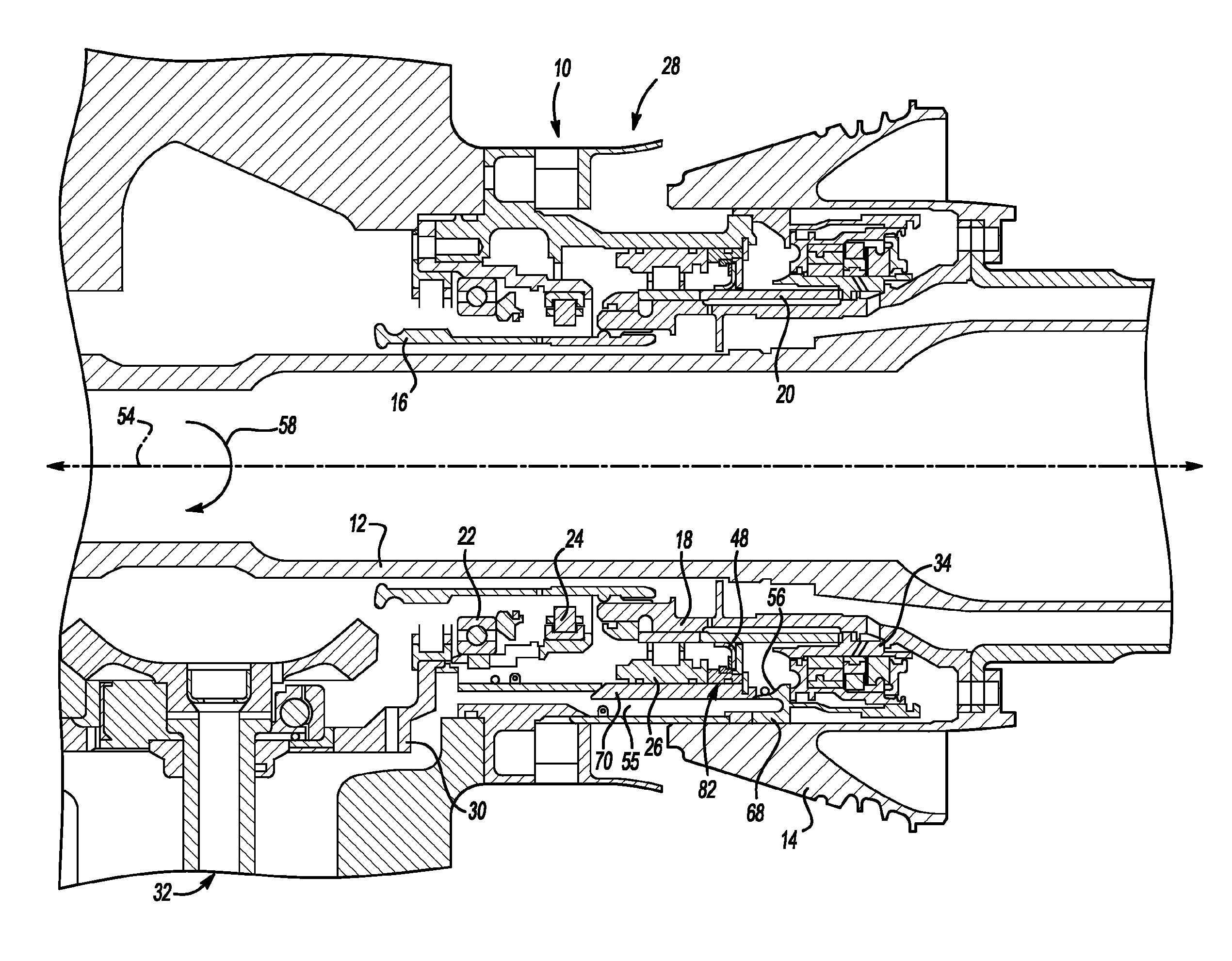
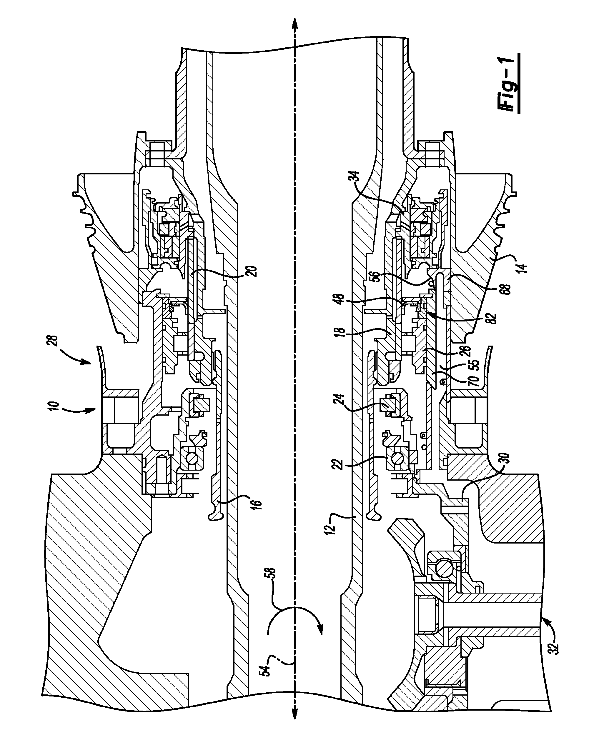
[0020]A plurality of different embodiments of the invention are shown in the Figures of the application. Similar features are shown in the various embodiments of the invention. Similar features have been numbered with a common reference numeral and have been differentiated by an alphabetic designation. Also, to enhance consistency, features in any particular drawing share the same alphabetic designation even if the feature is shown in less than all embodiments. Similar features are structured similarly, operate similarly, and / or have the same function unless otherwise indicated by the drawings or this specification. Furthermore, particular features of one embodiment can replace corresponding features in another embodiment unless otherwise indicated by the drawings or this specification.

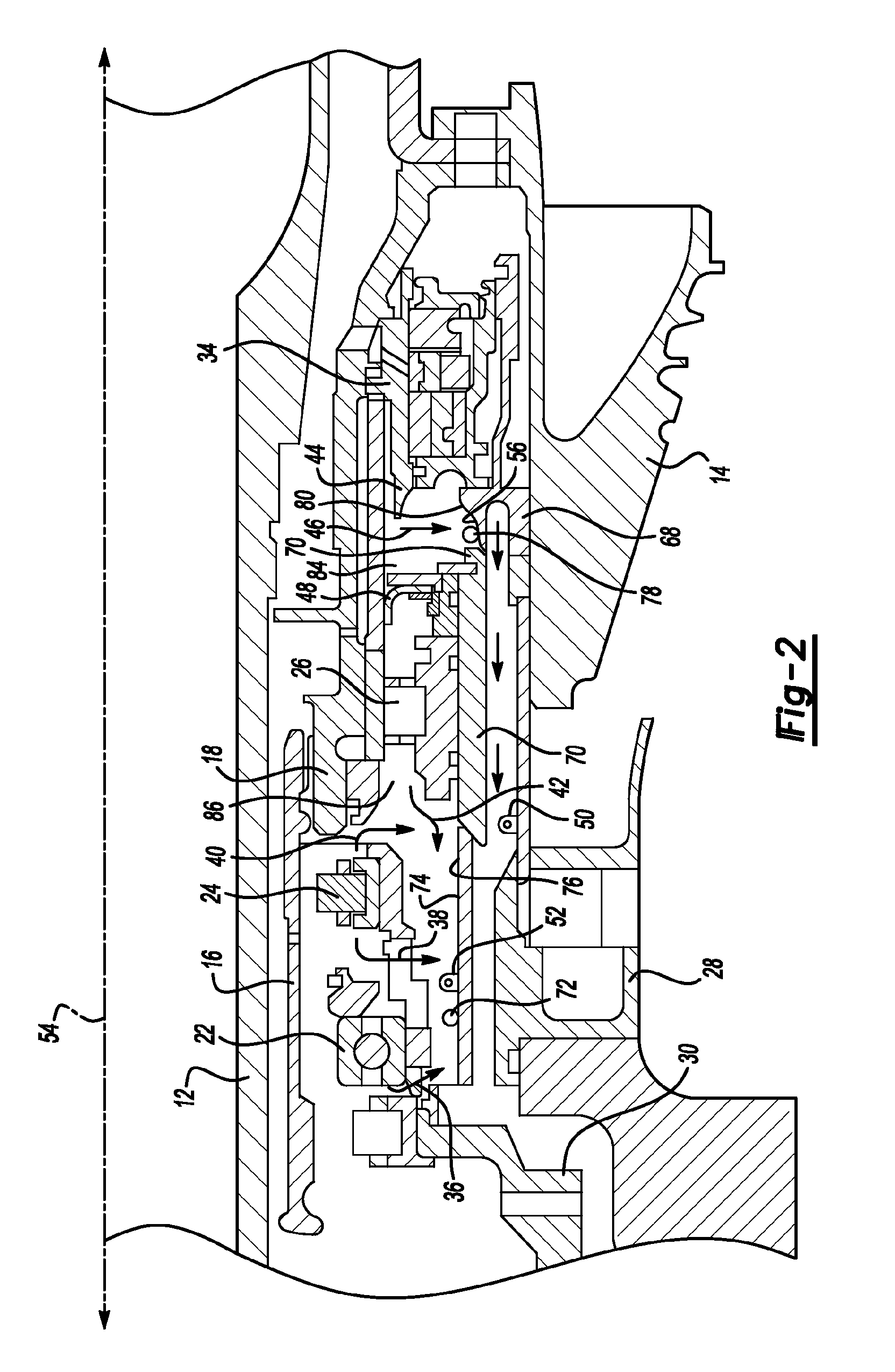
[0021]Lubricant flow in a sump housing can include both high momentum flow and low momentum flow. For example, a quantity of lubricant such as a droplet can be expelled from a rotating component in th...


PUM

PropertyMeasurementUnit
momentumaaaaaaaaaa
radial distanceaaaaaaaaaa
inner diameteraaaaaaaaaa

Abstract

A method and apparatus for scavenging lubricant is disclosed herein. In the invention, a rotating structure is encircled within a sump housing and subjected to lubrication. The sump housing collects high-momentum lubricant flow and low-momentum lubricant flow. The interior of the sump housing is separated into a plurality of chambers with at least one dynamic seal. The at least one dynamic seal extends between the sump housing and the rotating structure to isolate the high-momentum lubricant flow from the low-momentum lubricant flow.

Description

CROSS-REFERENCE TO RELATED APPLICATIONS[0001]This application claims the benefit of U.S. Provisional Patent Application Ser. No. 60 / 865,679 for a LUBRICATION SCAVENGE SYSTEM, filed on Nov. 14, 2006, and also claims the benefit of U.S. Provisional Patent Application Ser. No. 60 / 865,680 for a LUBRICATION SCAVENGE SYSTEM, filed on Nov. 14, 2006; both are hereby incorporated by reference in their entireties.BACKGROUND OF THE INVENTION[0002]1. Field of the Invention[0003]The invention relates to a system for scavenging lubricant from a lubricated component that supports a structure rotating at relatively high speed such as, for example, a shaft or bearing of a turbine engine.[0004]2. Description of Related Prior Art[0005]Structures rotating at relatively high speeds are found in many operating environments including, for example, turbine engines for aircraft and for power generation, turbochargers, superchargers, and reciprocating engines. The rotating structures in these operating envir...

Claims


Application Information

Patent Timeline
Patent Type & Authority Patents(United States)
IPC IPC(8): F01D25/18F01M1/12
CPCF01D25/183F02C7/06F05D2260/602
Inventor MUNSON, JOHN
Owner ROLLS ROYCE CORP
Why Eureka
Try Eureka