
Method for implanting a flowable fastener

a technology of flowable fasteners and fasteners, which is applied in the field of flowable fasteners, can solve the problems of reducing the overall force transmitting capability of the suture, reducing the strength of the suture, and difficulty in tying a knot, so as to increase the strength of the connection between the suture retainer and the sutur

Inactive Publication Date: 2011-02-01
P TECH
View PDF187 Cites 215 Cited by
  • Summary
  • Abstract
  • Description
  • Claims
  • Application Information

AI Technical Summary

Benefits of technology

This method enhances the suture's force transmission capability while minimizing tissue damage by distributing force evenly and preventing suture loosening, without the stress concentrations caused by knots.

Problems solved by technology

Difficulty has been encountered in securing sutures against movement relative to body tissue.
However, the knot weakens a portion of the suture and reduces the overall force transmitting capability of the suture.
In addition, a suture which is held by a knot applies force to a relatively small area of the body tissue and tends to cut or separate the body tissue.
Many operations are conducted in very restricted space where the tying of a knot is difficult.

Method used


Image

  • Method for implanting a flowable fastener
  • Method for implanting a flowable fastener
  • Method for implanting a flowable fastener

Examples


embodiment

of FIG. 20

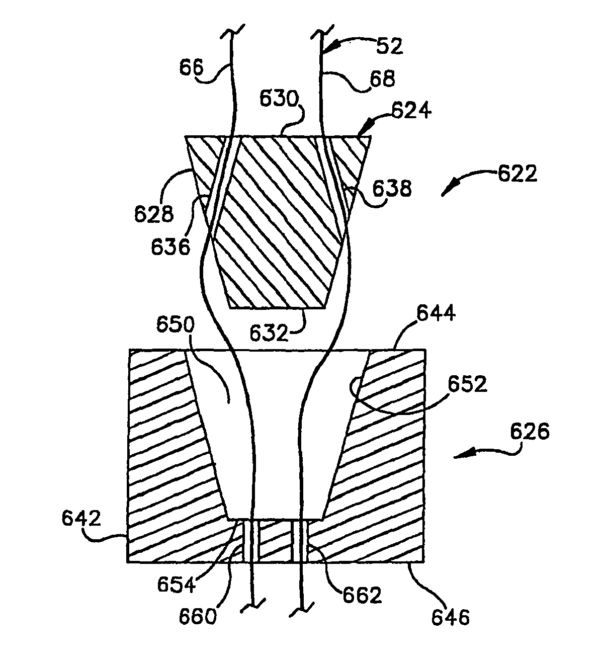
[0152]In the embodiment of the invention illustrated in FIGS. 17-19, the cylinder 316 is rotatable relative to the housing 314. In the embodiment of the invention illustrated in FIG. 20, cylinders are fixedly connected with the housing. Since the embodiment of the invention illustrated in FIG. 20 is similar to the embodiment of the invention illustrated in FIGS. 17-19, similar terminology will be utilized to identify similar components. It should be understood that one or more features of the embodiments of the invention illustrated in FIGS. 1-19 may be used with the embodiment of the invention illustrated in FIG. 20.

[0153]A suture retainer 356 includes a rectangular housing 358 which encloses a plurality of cylinders 360, 362, 364 and 366. The cylinders 360-366 have parallel central axes which extend parallel to flat rectangular upper and lower side walls 370 and 372 of the housing 358. Opposite end portions of the cylinders 360-366 are fixedly connected with rectangular ...


PUM


Abstract

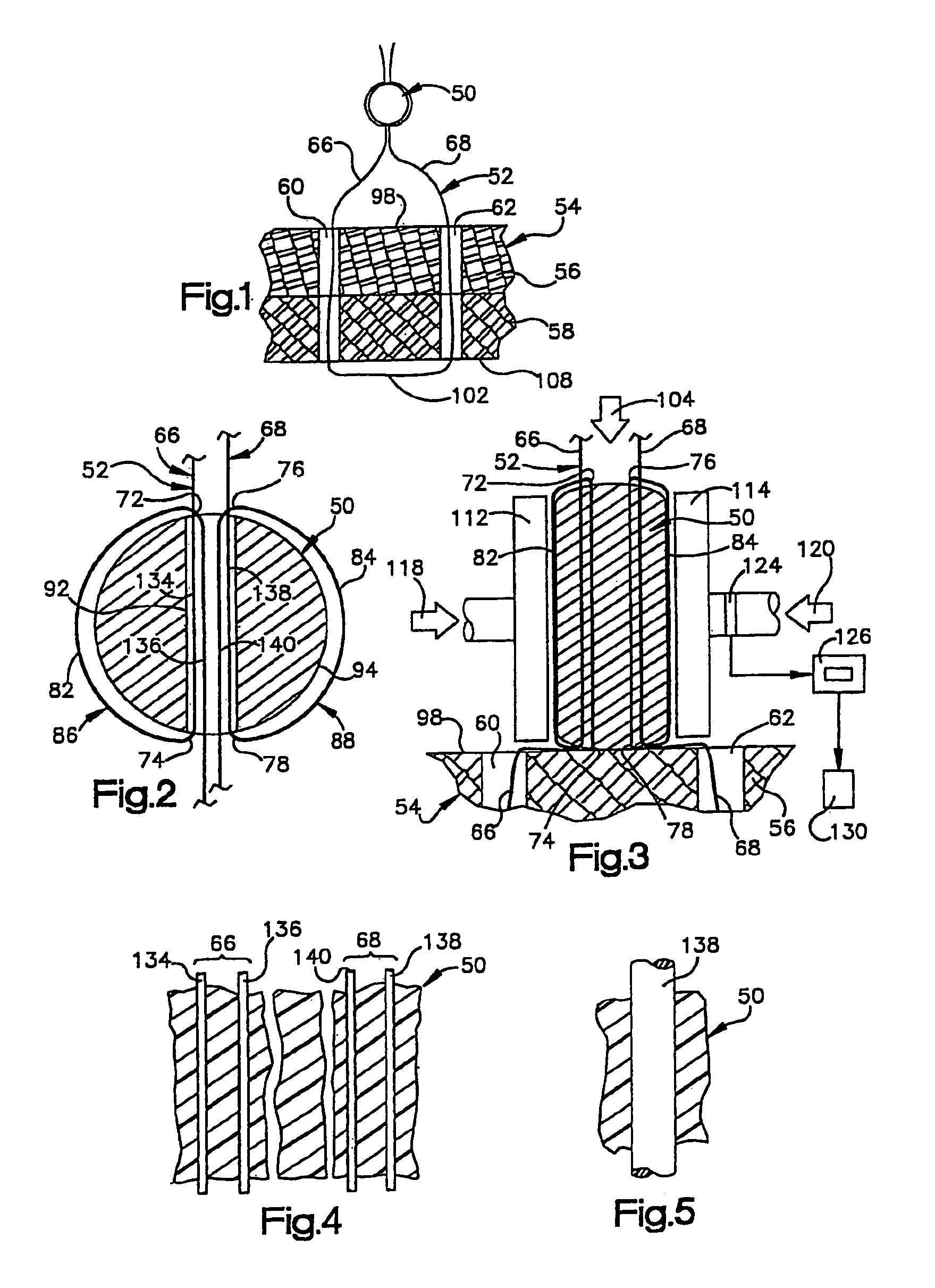
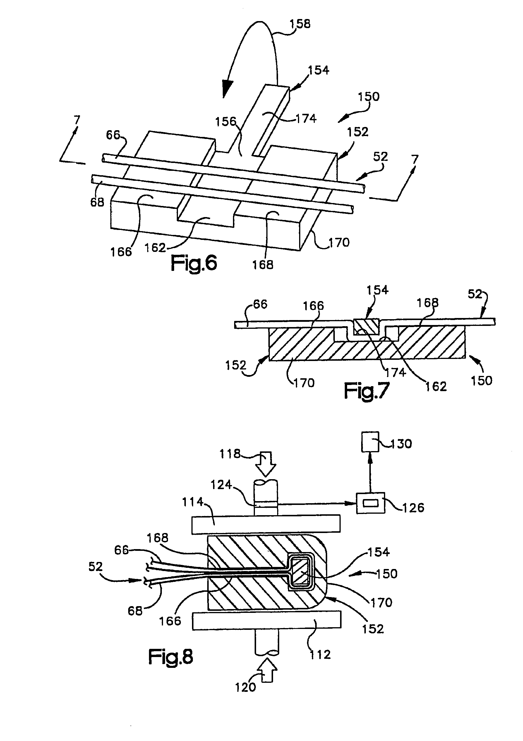
The present invention provides a method for securing an implant in the human body. The method includes providing a fastener having a substantially smooth outer surface and a conical shaped portion having a first end and a tapered end. The fastener is made of a polymeric material. The method also includes inserting the fastener in the body with the tapered end of the conical shaped portion leading the first end, heating the polymeric material of the fastener in the body, and applying pressure to the polymeric material of the fastener while heating to cause the polymeric material to flow in the body. Furthermore, the method includes collapsing the fastener with the heat and pressure to thereby secure the fastener relative to tissue in the body.

Description

CROSS-REFERENCE TO RELATED APPLICATION[0001]This application is a continuation of application Ser. No. 11 / 133,730 filed May 20, 2005. The aforementioned application Ser. No. 11 / 133,730 is itself a continuation of application Ser. No. 10 / 235,576 filed Sep. 5, 2002 now U.S. Pat. No. 7,147,652. The aforementioned application Ser. No. 10 / 235,576 is itself a divisional of application Ser. No. 09 / 429,100 filed Oct. 28, 1999, now U.S. Pat. No. 6,231,592. The aforementioned application Ser. No. 09 / 429,100 is itself a divisional of application Ser. No. 08 / 905,084 filed Aug. 1, 1997, now U.S. Pat. No. 6,010,525.FIELD OF THE INVENTION[0002]The present invention relates to a new and improved method and apparatus for securing a suture against movement relative to body tissue by using a retainer to grip the suture.BACKGROUND OF THE INVENTION[0003]Difficulty has been encountered in securing sutures against movement relative to body tissue. A knot may be tied in a suture to prevent loosening of the...

Claims


Application Information

Patent Timeline
Patent Type & Authority Patents(United States)
IPC IPC(8): A61B17/04
CPCA61B17/0487A61B2017/0445A61B2017/045A61B2017/0454A61B2017/0456A61B2017/0464A61B2017/0488A61B2017/0496
Inventor BONUTTI, PETER M.CREMENS, MATTHEW J.LIU, PING
Owner P TECH
Learn More