
Sheet cutting apparatus, sheet finisher provided therewith and image forming system equipped therewith

a technology of image forming system and sheet cutting apparatus, which is applied in the direction of electrographic process apparatus, instruments, optics, etc., can solve the problems of abnormally high load on the cutting blade, large apparatus, and large power consumption, and achieve the effect of deteriorating the quality of the cut edge surfa

Active Publication Date: 2011-02-15
KONICA MINOLTA BUSINESS TECH INC
View PDF18 Cites 4 Cited by
  • Summary
  • Abstract
  • Description
  • Claims
  • Application Information

AI Technical Summary

Benefits of technology

The apparatus achieves efficient cutting with reduced power consumption, maintaining high quality cut edges and booklet alignment, even with large sheet bundles, by optimizing the cutting mechanism and load distribution.

Problems solved by technology

And also, since it is necessary to set the power of the driving section at the maximum value in the usable range, there is the requirement for a large power and large sized motor and a power supply with a large power capacity resulting in the problems that not only the apparatus becomes large but also the power consumption becomes large.
In particular, it becomes difficult to incorporate a sheet cutting apparatus in a sheet finishing apparatus that is a part constituting an image forming system.
In particular, at the time of cutting a number of sheets of paper such as when cutting 50 to 100 sheets, an abnormally high load may be applied on the cutting blade.
Because of this, the driving load of the cutting blade moving section becomes large.
In addition, the cut edge surface of the bundle of sheets does not become perpendicular to the sheet surface and the sheets do not become aligned, thereby lowering the quality of the finished booklets.

Method used


Image

  • Sheet cutting apparatus, sheet finisher provided therewith and image forming system equipped therewith
  • Sheet cutting apparatus, sheet finisher provided therewith and image forming system equipped therewith
  • Sheet cutting apparatus, sheet finisher provided therewith and image forming system equipped therewith

Examples


Embodiment Construction

[0023]A preferred embodiment of the present invention will be described while referring to the drawings, as follows.

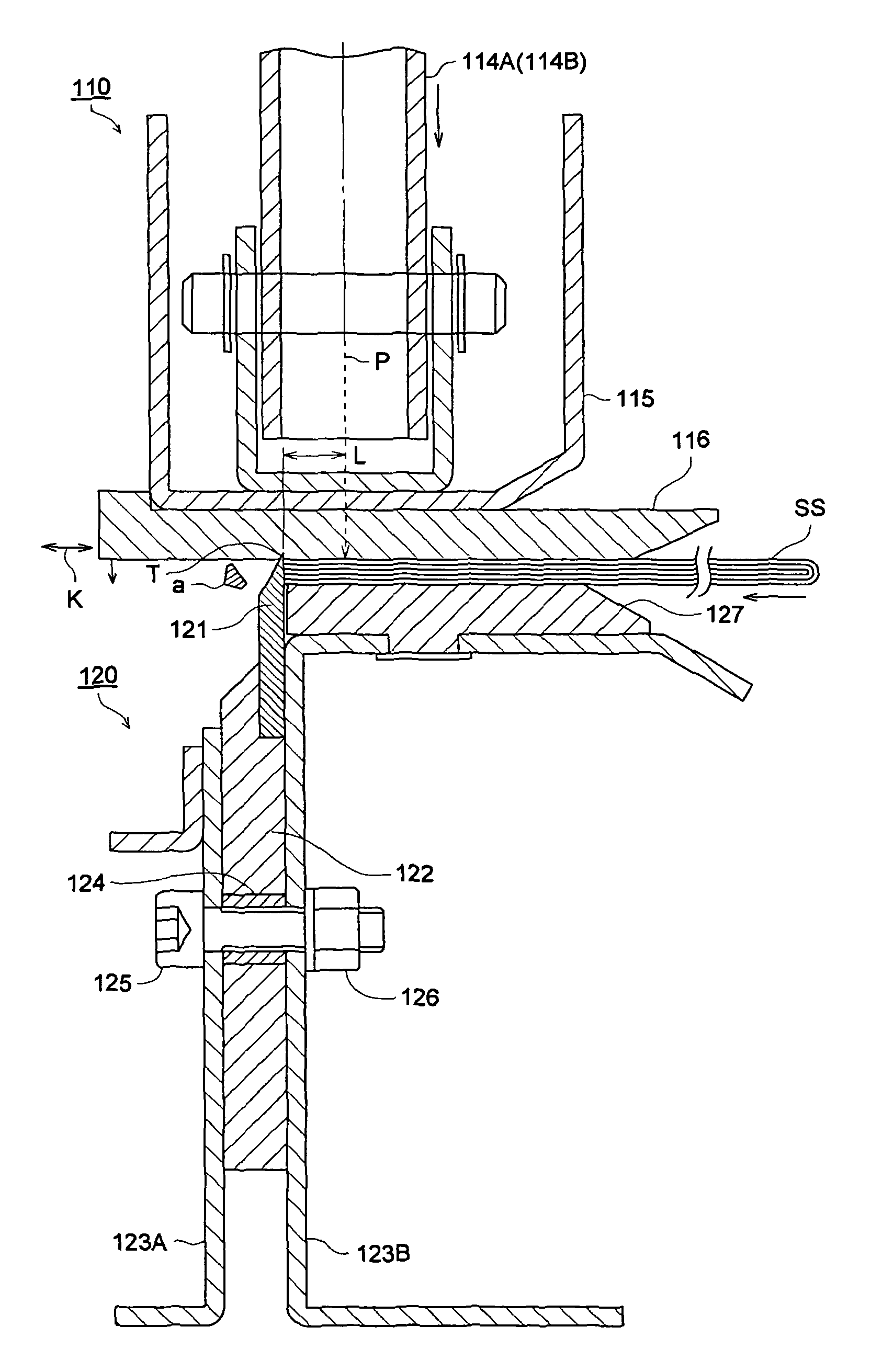
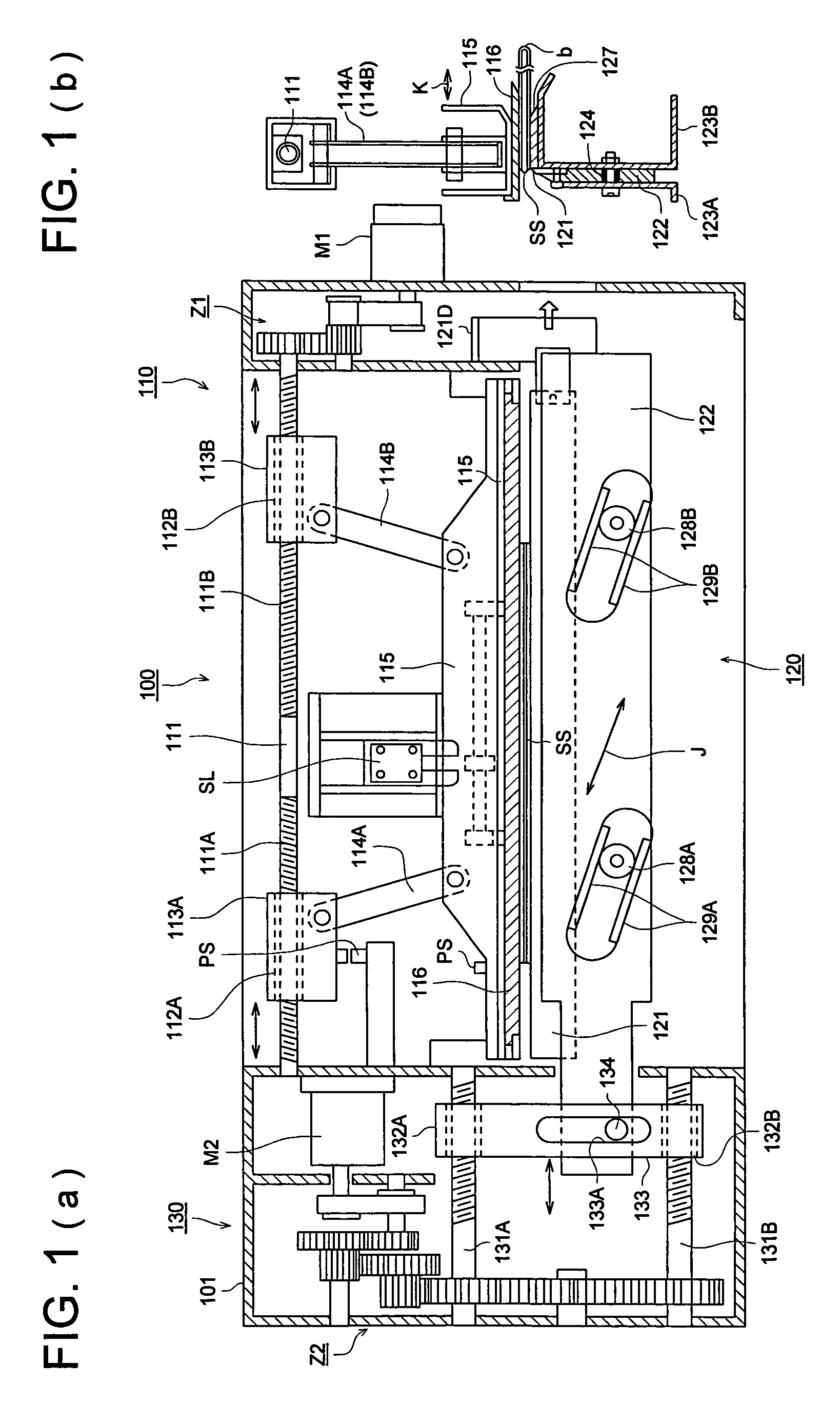
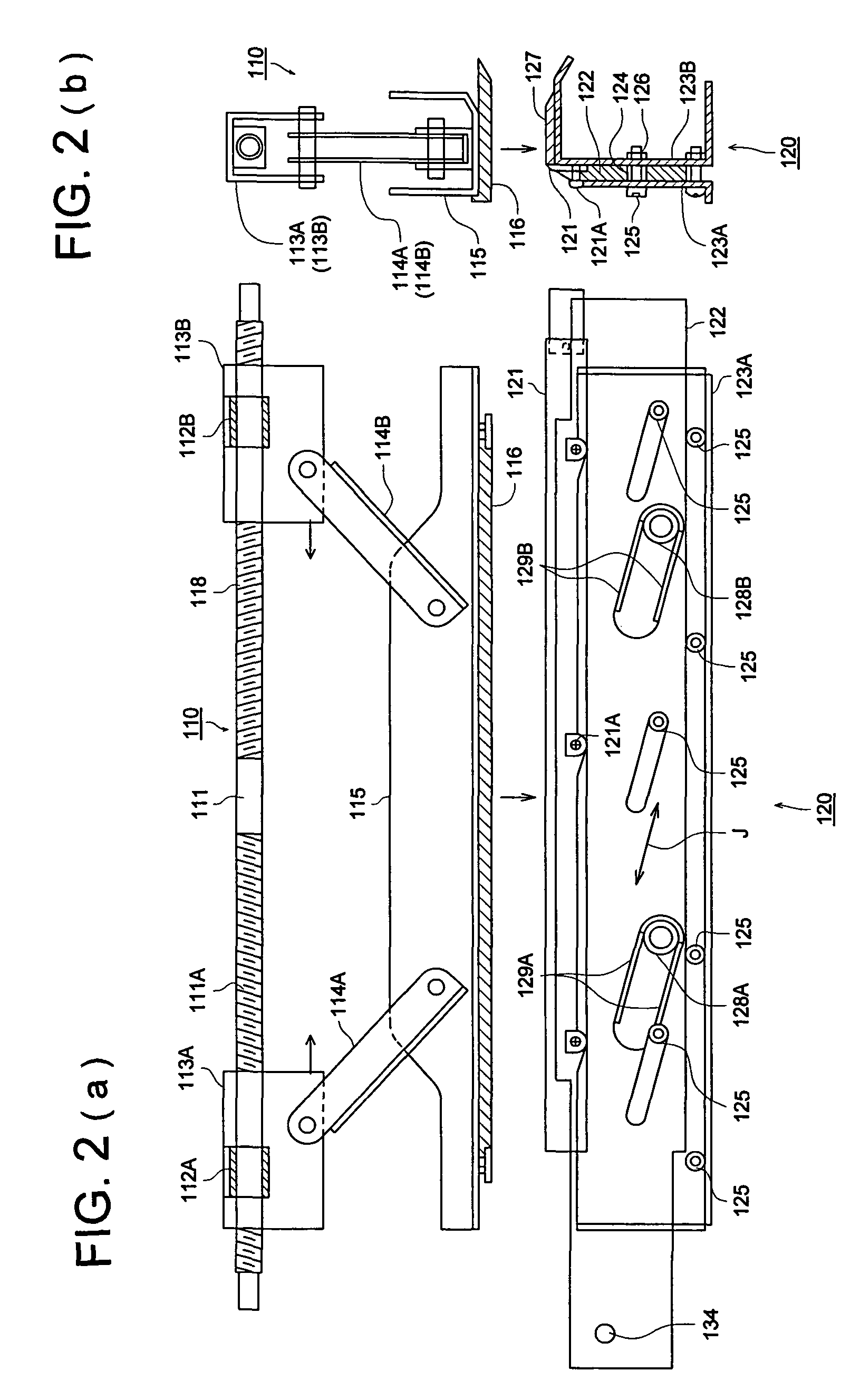
[0024]FIG. 1(a) is the front view of the sheet cutting apparatus according to the embodiment and FIG. 1(b) is the side view of its important parts. FIG. 2(a) is the front view of the important parts showing the standby state of the sheet cutting apparatus and FIG. 2(b) is the side view of its important parts. FIG. 3(a) is the front view of the important parts showing the sheet cutting starting state of the sheet cutting apparatus and FIG. 3(b) is the side view of its important parts. FIG. 4(a) is the perspective view of the important parts of the cutting blade moving section 120 and FIG. 4(b) is the cross-sectional view of the important parts of the cutting blade moving section 120.

[0025]In FIGS. 1(a) and 1(b), the cutting blade receiving member moving section 110 is placed on top of the body 101 of the sheet cutting apparatus 100, the cutting blade moving section 120 ...


PUM

PropertyMeasurementUnit
thicknessaaaaaaaaaa
distanceaaaaaaaaaa
distance L1aaaaaaaaaa

Abstract

A sheet cutting apparatus includes: a cutting blade for cutting an edge of a sheet bundle conveyed to a cutting position of the sheet bundle; a cutting blade moving section for moving obliquely the cutting blade with respect to a sheet surface of the sheet bundle; a fixed supporting table for supporting the sheet bundle in a vicinity of the cutting position; a blade receiving member for pressing the sheet bundle and receiving the cutting blade in the vicinity of the cutting position; and a blade receiving member moving section for ascending or descending the blade receiving member. A center position of a load application action of the blade receiving member by the blade receiving member moving section, is set to a position upstream of the sheet cutting position in a conveying direction of the sheet bundle, and in the vicinity of the sheet cutting position.

Description

[0001]This application claims priority from Japanese Patent Application No. 2004-299765 filed on Oct. 14, 2004, which is incorporated hereinto by reference.BACKGROUND OF THE INVENTION[0002]The present invention relates to a sheet cutting device that cut several sheets of paper, to a sheet finishing apparatus equipped with the sheet cutting device, and to an image forming systems provided with the sheet finishing apparatus.[0003]A Sheet finisher carrying out various types of finishing is connected to a high speed image forming apparatus such as an image forming apparatus employing the electro-photography method, and multiple-functional image forming systems have come into wide use that make it possible to carry out within a single apparatus various types of finishing operations such as stapling and folding of paper sheets on which images have been formed.[0004]Among the different types of finishers there is the sheet cutting apparatus that aligns the edges of a bundle of a plurality ...

Claims


Application Information

Patent Timeline
Patent Type & Authority Patents(United States)
IPC IPC(8): B26D5/20B26D5/00B26D7/02B26D5/08
CPCB26D7/025G03G15/6582G03G2215/00814Y10T83/8874Y10T83/7487Y10T83/50Y10T83/566Y10T83/887
Inventor KANEKO, MASAHIROSHIDA, TOSHIOWAKABAYASHI, HIROYUKI
Owner KONICA MINOLTA BUSINESS TECH INC
Learn More