
Apparatus and methods for inspecting tape lamination

a tape lamination and apparatus technology, applied in the field of tape lamination machines, can solve the problems of difficult to find a line of sight to a compaction point for inspection purposes, the taped area close to the compaction shoe can be particularly difficult to inspect, and the machine is often down

Inactive Publication Date: 2011-02-15
THE BOEING CO
View PDF88 Cites 43 Cited by
  • Summary
  • Abstract
  • Description
  • Claims
  • Application Information

AI Technical Summary

Benefits of technology

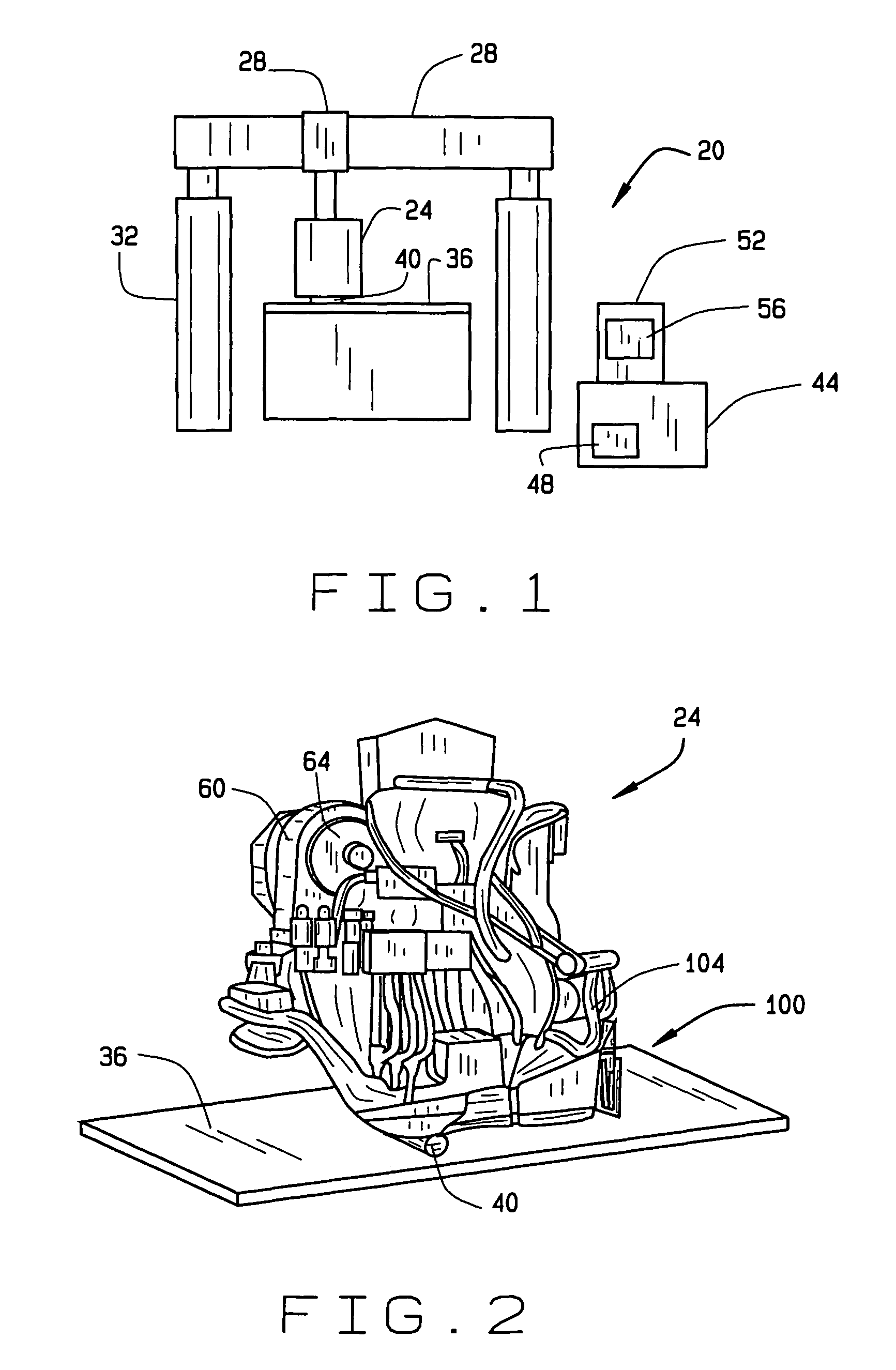
The present invention is a system for inspecting composite material laid onto a substrate by a lamination machine. The system includes an imaging assembly attached to the delivery head of the machine, which obtains an image of the laid material beneath the imaging assembly. A processor inspects the image to detect any flaws in the material. The system can also detect the location of the flaw and the removal of the backing from the material. The invention allows for efficient inspection of composite materials during the lamination process.

Problems solved by technology

Visual inspection, however, can result in considerable machine down time.
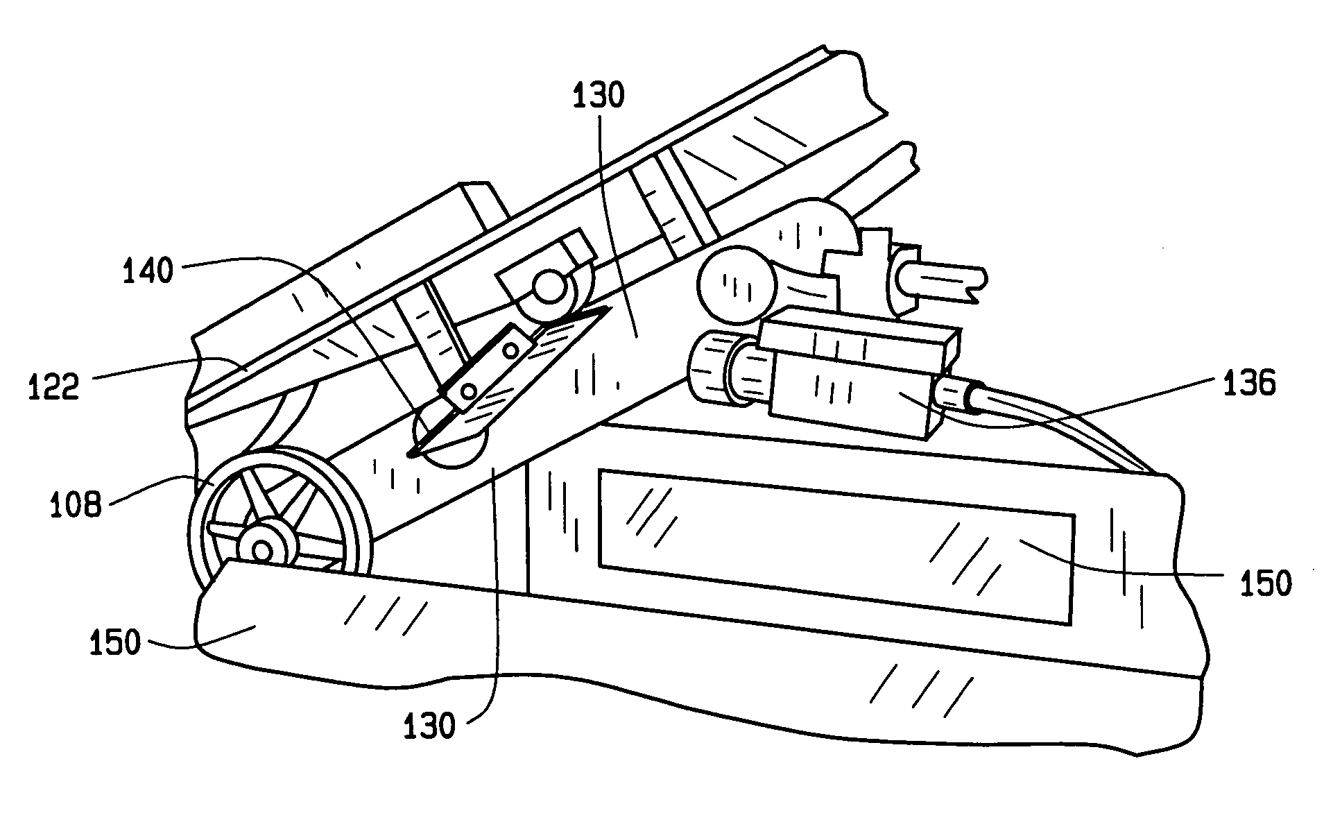
Inspection of taped areas close to the compaction shoe can be particularly difficult, because a typical CTLM delivery head has a low profile in relation to the substrate onto which tape is being laid.
Thus the shape of the delivery head makes it difficult to find a line of sight to a compaction point for inspection purposes.

Method used


Image

  • Apparatus and methods for inspecting tape lamination
  • Apparatus and methods for inspecting tape lamination
  • Apparatus and methods for inspecting tape lamination

Examples


Embodiment Construction

[0023]The following description of the preferred embodiment(s) is merely exemplary in nature and is in no way intended to limit the invention, its application, or uses. For purposes of clarity, the same reference numbers may be used in the drawings and this description to identify similar elements. The term “processor” can include but is not limited to one or more processors, computers, microcomputers, application specific integrated circuits (ASICs), electronic circuits, combinational logic circuits, and / or other suitable components that provide the described functionality. Although configurations of the present invention are described with reference to a contour tape lamination machine (CTLM), the invention is not so limited. Embodiments also are contemplated in connection with other types of lamination machines, including but not limited to flat tape lamination machines, and in connection with other automated material placement machines and processes.

[0024]An exemplary configurat...


PUM

PropertyMeasurementUnit
widthsaaaaaaaaaa
widthaaaaaaaaaa
areaaaaaaaaaaa

Abstract

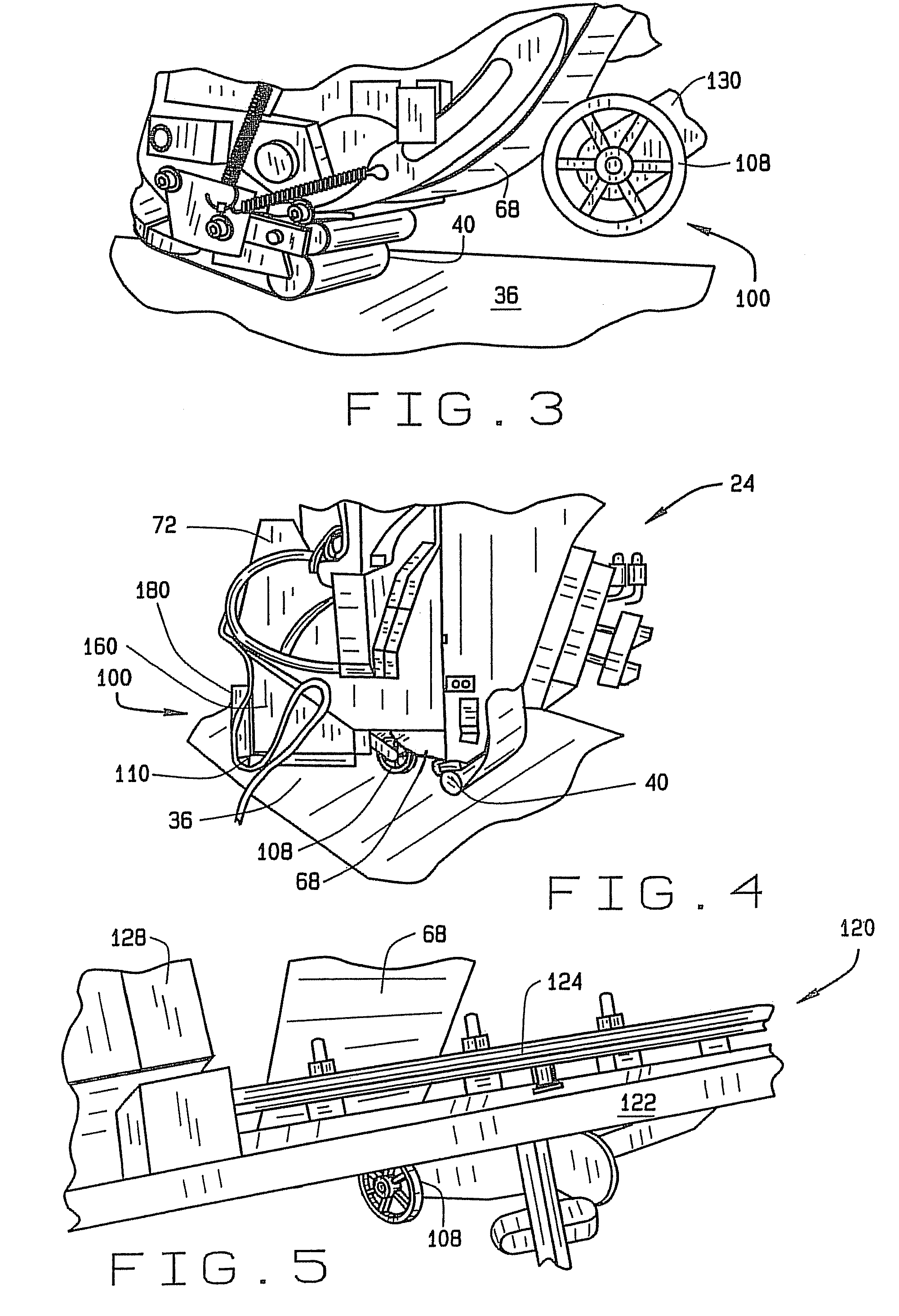
A system for inspecting a composite material laid onto a substrate by a lamination machine. An imaging assembly attached to a rear portion of a delivery head of the machine obtains an image of at least a portion of the laid material beneath the imaging assembly. A processor inspects the image to detect a flaw. This system can provide an image of laid tape obtained close to a tape compaction point and can be implemented as a retrofit or as original equipment in lamination machines.

Description

FIELD OF THE INVENTION[0001]The present invention relates generally to using a tape lamination machine to fabricate composite structures. More particularly, but not exclusively, the present invention relates to systems and methods for detecting and marking inconsistencies in tape laid by a tape lamination machine.BACKGROUND OF THE INVENTION[0002]Automated tape lamination is widely used in aerospace and other industries in the fabrication of large composite structures. A contour tape lamination machine (CTLM) may be used to lay composite tape in courses and plies onto a substrate. The tape is laid by a delivery head suspended from a gantry structure over the substrate. Tape may be applied in widths, for example, of six or twelve inches. A compaction shoe of the delivery head compacts the tape onto the substrate.[0003]During the tape placement process, courses of laid tape typically are inspected for flaws such as gaps, overlaps and foreign objects. Visual inspection, however, can res...

Claims


Application Information

Patent Timeline
Patent Type & Authority Patents(United States)
IPC IPC(8): G06K9/00G01N21/84G01N21/00
CPCG01N21/8806B29C70/388G01N2021/8411G01N2021/8472G01N2021/8838G01N2201/0612
Inventor ENGELBART, ROGER WHANNEBAUM, REEDHENSLEY, BRIAN SPOLLOCK, TIMOTHY TORR, SAMUEL D
Owner THE BOEING CO
Learn More