Panel, in particular for floor covering

a technology for flooring and panels, applied in flooring, wood layered products, transportation and packaging, etc., can solve the problems of affecting the effect of the material strength and the intensity of the click effect, placing a greater or lesser load on the strip,

Inactive Publication Date: 2011-02-22
TARKETT SAS (FR)
View PDF5 Cites 24 Cited by
  • Summary
  • Abstract
  • Description
  • Claims
  • Application Information

AI Technical Summary

Benefits of technology

[0017]The panel according to the present invention makes use of coupling elements designed for angular interlocking essentially without elastic deformation which are comparable in this respect to those of the conventional Terbrack system. According to one important aspect of the invention, at least one of the coupling elements is provided with a repositionable adhesive in order to fasten together two identical panels joined by their respective coupling means. In this manner, angular interlocking with a “click” effect is obtained essentially without elastic deformation of the coupling elements and the panels, so enabling assembly / disassembly of the panels without jeopardising their integrity.
[0044]In this context, it will be appreciated that the panel according to the invention makes it possible to achieve a “click” effect even with materials which, unlike wood, HDF or chipboard, do not have any real elasticity. Such materials, which may for certain applications prove to be serious competitors to HDF, are for example fibre cements or certain highly filled resins which can readily be machined (in order to produce an angular interlocking profile) but have no elasticity.

Problems solved by technology

Furthermore, the forces in play during the click action will place a greater or lesser load on the strip at the point where it is generally at its thinnest.
It may therefore readily be understood that, in the case of thin products, for example of the HDF type, it becomes tricky to reconcile the strength of the material with the intensity of the “click” effect.

Method used


Image

  • Panel, in particular for floor covering
  • Panel, in particular for floor covering
  • Panel, in particular for floor covering

Examples


Embodiment Construction

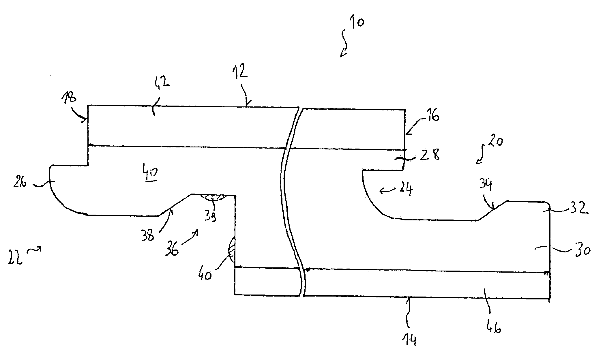
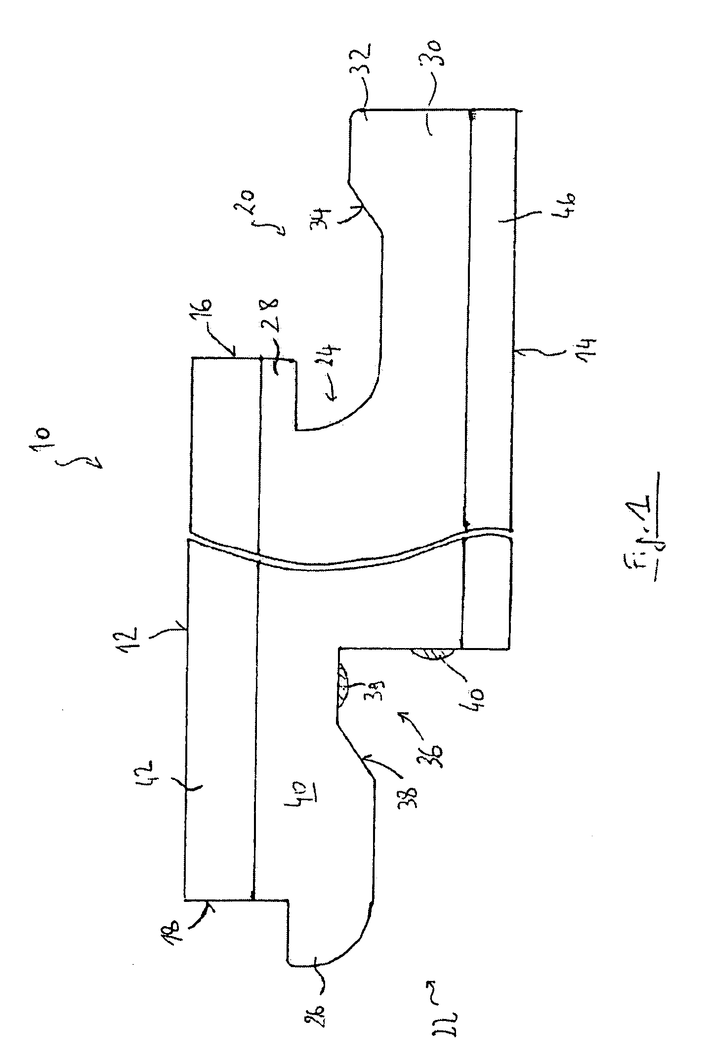
[0051]FIG. 1 shows a cross-sectional view of a preferred embodiment of a panel 10 according to the invention. In the present variant, the panel 10 is a floor covering panel for producing floating flooring. This panel, which is commonly known as a strip or board, is generally rectangular in shape and conventionally comprises an upper face 12, an opposing lower face 14 intended to rest in the assembly plane, together with two opposing lengthwise edges 16 and 18 respectively provided with coupling means 20 and 22 to be joined to other similar panels. The small sides are also provided with such coupling means.

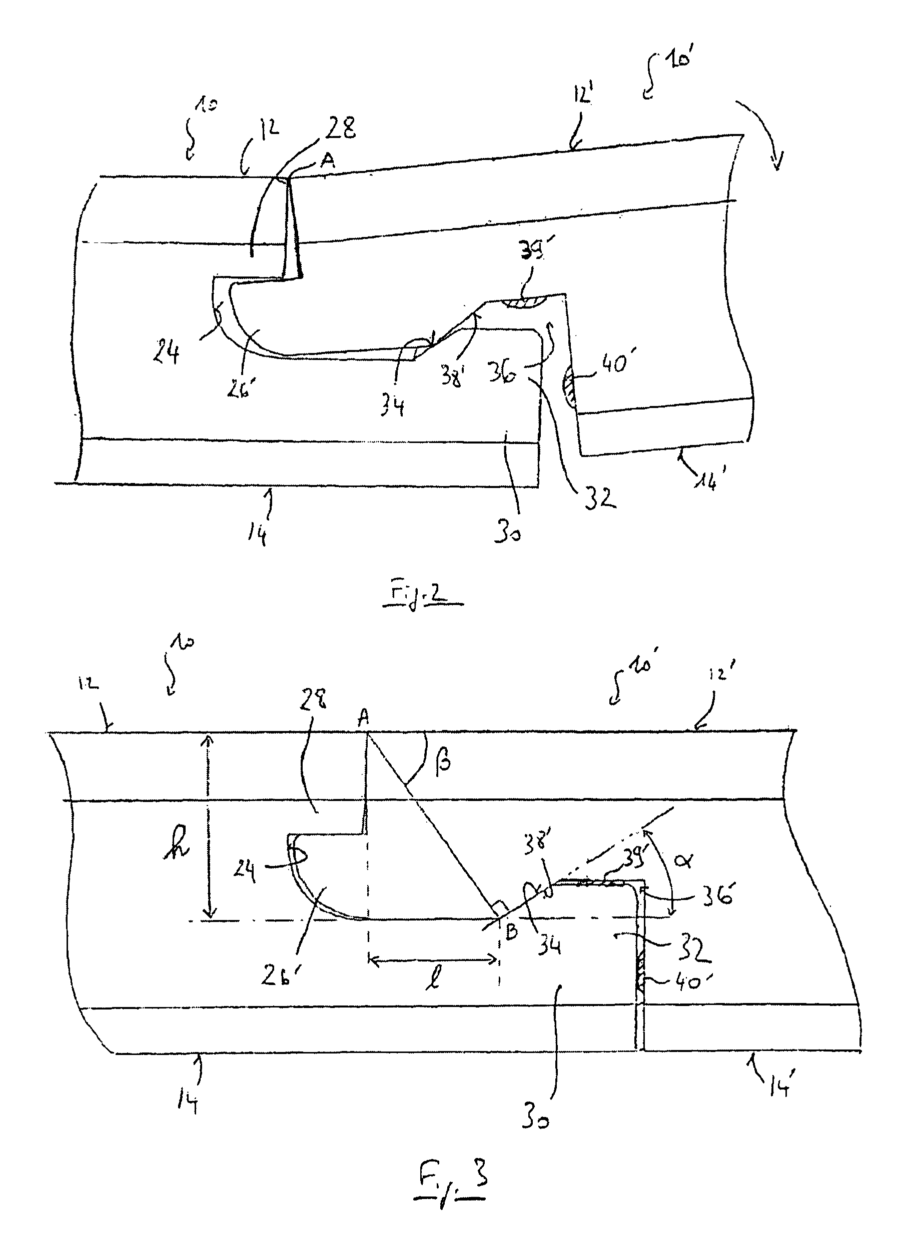
[0052]The first coupling means 20 comprises a groove 24 and the second coupling means 22 is provided with a tongue 26. Conventionally, these coupling means 20 and 22 are designed so as to be able to cooperate together for assembling the panel 10 with other panels of this type.

[0053]The groove 24 of the first coupling means is defined by an upper lip 28 and a lower lip 30 which exte...


PUM

PropertyMeasurementUnit
locking angleaaaaaaaaaa
angleaaaaaaaaaa

Abstract

Disclosed is a surface covering panel including a first edge with a groove inclusive first coupling means, a second opposite edge with a tongue inclusive second coupling means, the coupling means enabling coupling of two panels, a mechanical locking means integrated into at least one of the coupling means which, when two panels are coupled, is configured to prevent these panels from moving apart, the coupling means being designed for coupling essentially without elastic deformation, wherein at least one part of the surface of at least one of the coupling means includes a repositionable adhesive configured to create bonds between the coupling means that are multiply breakable and re-bondable, wherein a breaking of the bonds on disassembly of the panels results in a chemical click designed to indicate decoupling to a user.

Description

[0001]This application is the national stage entry of PCT / EP2006 / 063154 filed Jun. 13, 2006.FIELD OF THE INVENTION[0002]The present invention relates in general to surface covering panels. It relates more particularly to “floating” flooring systems and in particular panels, commonly known as strips or boards, for producing such flooring systems.BACKGROUND OF THE INVENTION[0003]Floating flooring systems have been increasing considerably in popularity in recent years. Unlike nailed or glued flooring systems, the laying of which is difficult and has to be left to specialists, a particular advantage of floating flooring systems is their ease of installation (on an existing floor covering of the carpet, ceramic tile or vinyl type or directly onto a stone floor).[0004]As is known, flooring strips are conventionally provided on their edges with tongue and groove coupling elements which are intended to join two adjacent strips together by interlocking during assembly of the flooring system....

Claims


Application Information

Patent Timeline
Patent Type & Authority Patents(United States)
IPC IPC(8): B32B21/00E04F15/00E04F15/04
CPCE04F13/08E04F15/02E04F15/04E04F2201/0153Y10T428/17Y10T428/249921Y10T428/249923Y10T428/19E04F2201/07
Inventor BATHELIER, XAVIERDECONINCK, BERNARD-ANDRE
Owner TARKETT SAS (FR)
Why Eureka
Try Eureka