Cooling system

a cooling system and electronic equipment technology, applied in the direction of instruments, furniture parts, electric apparatus casings/cabinets/drawers, etc., can solve the problems of inefficient cooling, inefficient cooling, and inefficient hot/cold aisle cooling of electronic equipment,

Inactive Publication Date: 2011-03-15
PANDUIT
View PDF43 Cites 73 Cited by
  • Summary
  • Abstract
  • Description
  • Claims
  • Application Information

AI Technical Summary

Problems solved by technology

When in use, the electronic equipment housed in the cabinets generates heat that must be extracted or damage to the equipment can result.
Although it is reasonably effective, the hot aisle / cold aisle method of cooling electronic equipment can be very inefficient and has various drawbacks.
If equipment is added or changed, or if a tile is accidentally moved or covered up, inefficient cooling results and cooling must be increased.
Finally, since the flow of cool air is not directed to the equipment that needs cooling, any change in the room configuration or even people standing in the aisles can disrupt the cool air flow.
These disruptions result in a smaller portion of the cool air actually cooling the equipment, which further decreases efficiency.
The inefficiencies of the hot aisle / cold aisle system lead to wasted energy (e.g. electricity to power the air conditioners), due to the need to “overcool” the data center to make up for cooling losses.
In addition, data loss and downtime can result due to equipment damage from overheating.

Method used


Image

  • Cooling system
  • Cooling system
  • Cooling system

Examples


Embodiment Construction

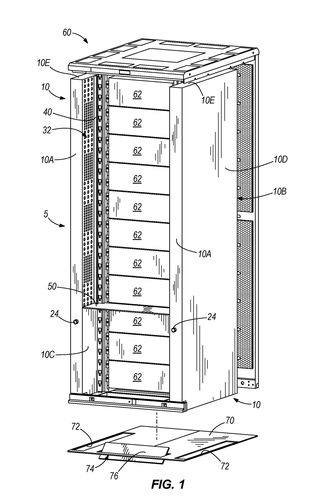
[0023]Referring to FIGS. 1-2, one example of a cabinet cooling system 5 is shown installed in an electronic equipment cabinet 60 (the front door and side panels of cabinet 60 are removed for clarity). As shown and described herein, cabinet 60 is a network cabinet, such as that shown and described in co-pending U.S. patent application Ser. Nos. 11 / 467,956, 11 / 538,884, 11 / 559,708, 11 / 623,358, 11 / 623,839, and 11 / 683,052, which are incorporated herein by reference. However, it will be understood that cooling system 5 can be used with any type of cabinet that is adapted to carry electronic equipment, such as servers.

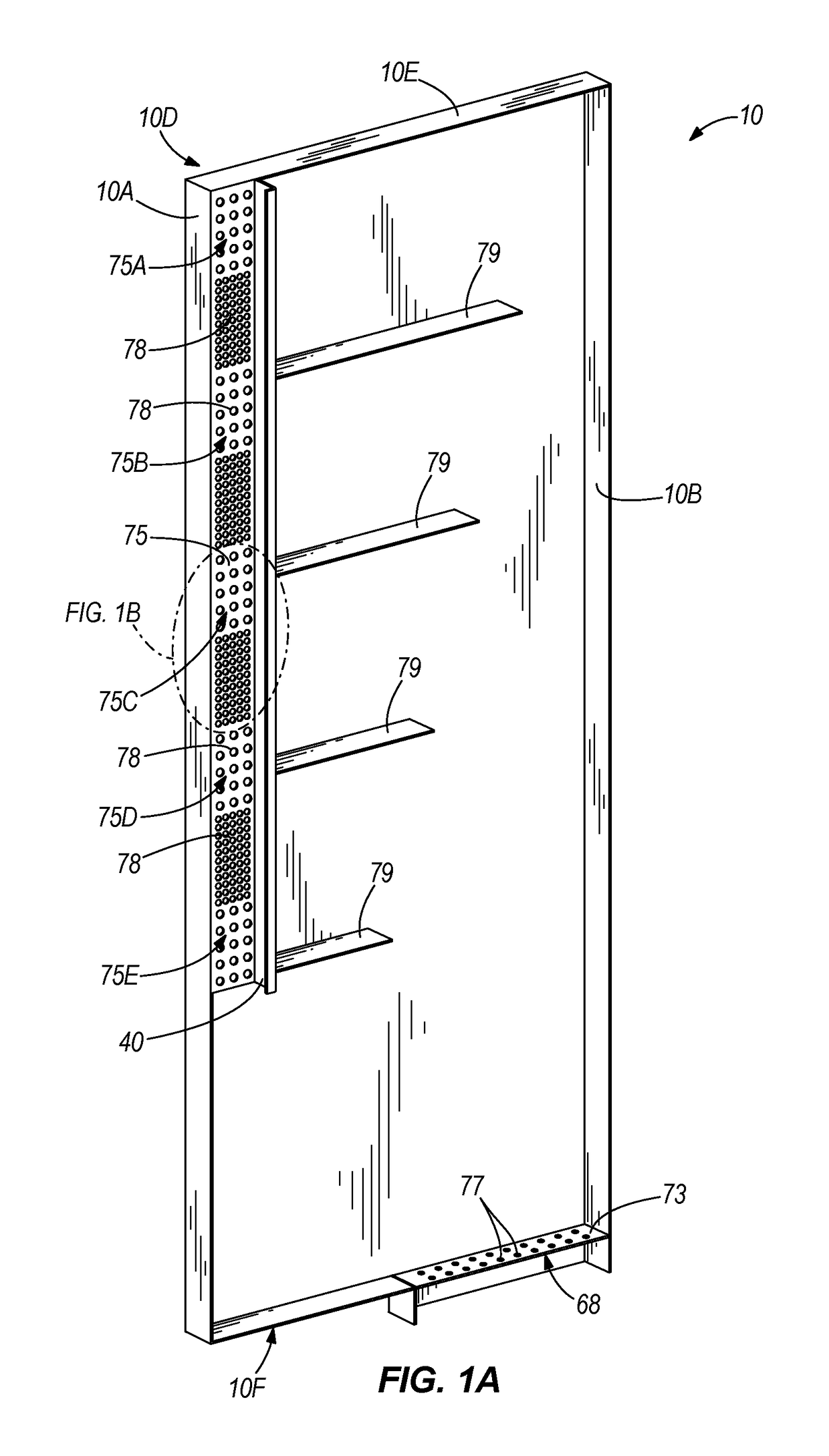
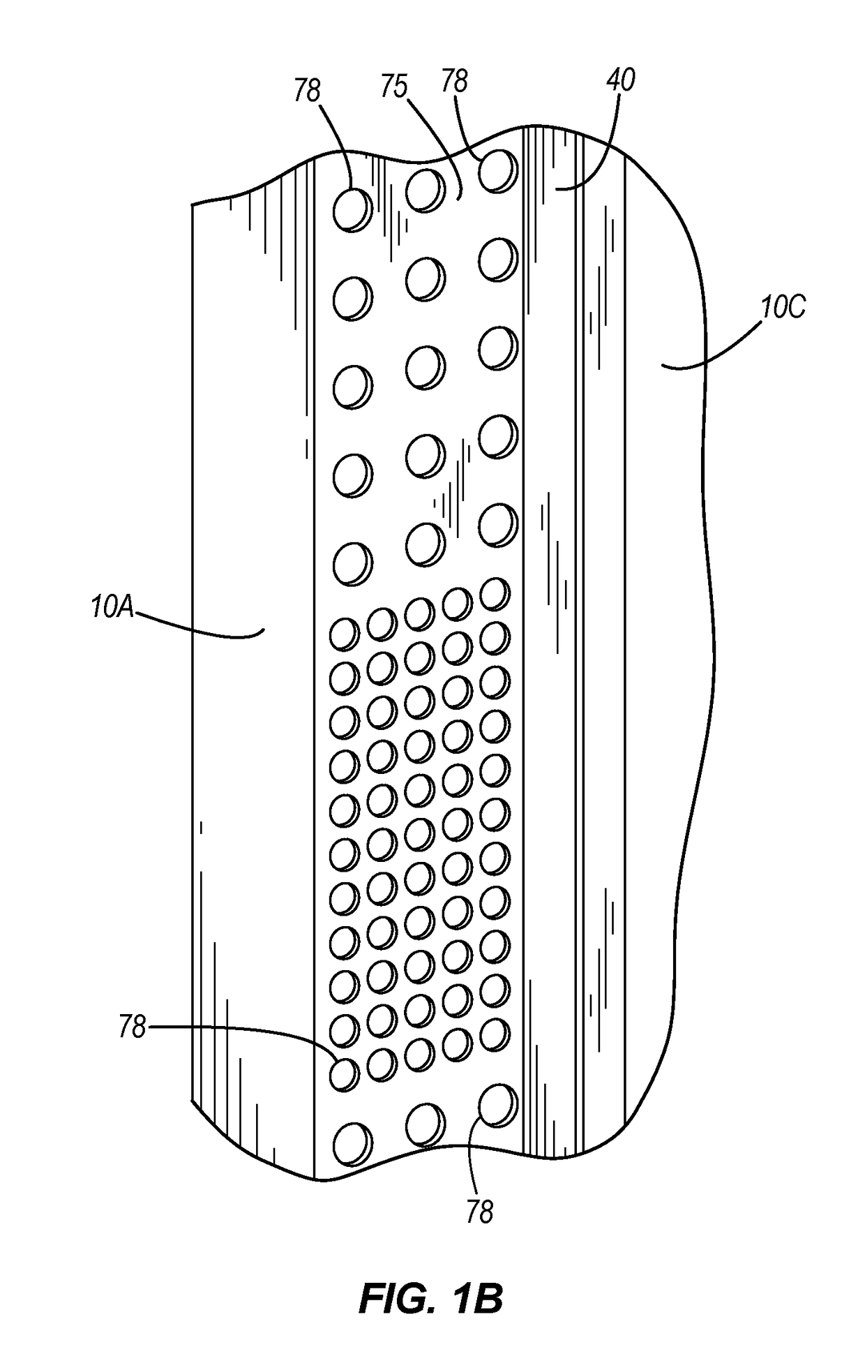
[0024]In this example, cooling system 5 is generally made up of ducts 10, which are minor images of each others and shelf 50. Each duct 10 is generally rectangular and is formed by front wall 10A, back wall 10B, inside wall 10C, outside wall 10D, top wall 10E, and a bottom wall (not shown). As used herein, inside wall 10C is the wall of duct 10 that faces electronic equipment...


PUM


Abstract

An electronic equipment cabinet configured to support electronic equipment is provided and may include a shelf positioned in the cabinet separating the cabinet into a first zone and a second zone. The first and second zones may be in fluid communication with a cool air source. In some examples, the first zone may receive cool air directly from a cool air source and the second zone may receive cool air from a duct in fluid communication with the cool air source. In another example, both the first and second zones may receive cool air from the cool air source through a duct. In yet other examples, the cabinet may include a baffle between the cool air source and one of the first zones and the second zones to selectively control a quantity of cool air provided to the one of the first and second zones.

Description

RELATED APPLICATIONS[0001]The present application claims the benefit of U.S. Provisional Patent Application No. 60 / 986,630, filed Nov. 9, 2007, the entire contents of which are hereby incorporated by reference.FIELD OF INVENTION[0002]This invention relates to systems and methods for cooling electronic equipment in equipment cabinets. In particular, the invention relates to ducted cooling systems for directing cooled air through equipment cabinets for cooling electronic equipment.BACKGROUND[0003]In a typical data center, equipment cabinets are used to hold various types of electronic equipment, such as servers and other mission-critical data-processing equipment. When in use, the electronic equipment housed in the cabinets generates heat that must be extracted or damage to the equipment can result. As equipment densities in the cabinets increase, so do the heat extraction (cooling) needs. Today, in a typical data center, it is not unusual for electronic equipment to generate 10 kilow...

Claims


Application Information

Patent Timeline
Patent Type & Authority Patents(United States)
IPC IPC(8): H05K7/20G06F1/20
CPCH05K7/20572H05K7/20736
Inventor CAVENEY, JACK E
Owner PANDUIT
Why Eureka
Try Eureka