Fender protector structure

a technology of fender protector and fender, which is applied in the direction of bumpers, roofs, manufacturing tools, etc., can solve the problems of insufficient rigidity at the the inability to establish a fixing point at the vehicle side at a peripheral intermediate portion of the wheel arch portion, and the structure still lacks sufficient rigidity

a technology of fender protector and fender, which is applied in the direction of bumpers, roofs, manufacturing tools, etc., can solve the problems of insufficient rigidity at the the inability to establish a fixing point at the vehicle side at a peripheral intermediate portion of the wheel arch portion, and the structure still lacks sufficient rigidity

US7909392B2Active Publication Date: 2011-03-22NISSAN MOTOR CO LTD

Image

  • Fender protector structure
  • Fender protector structure
  • Fender protector structure

Examples


Embodiment Construction

[0020]Hereinafter, embodiments of the present disclosure will be explained in detail with reference to the drawings.

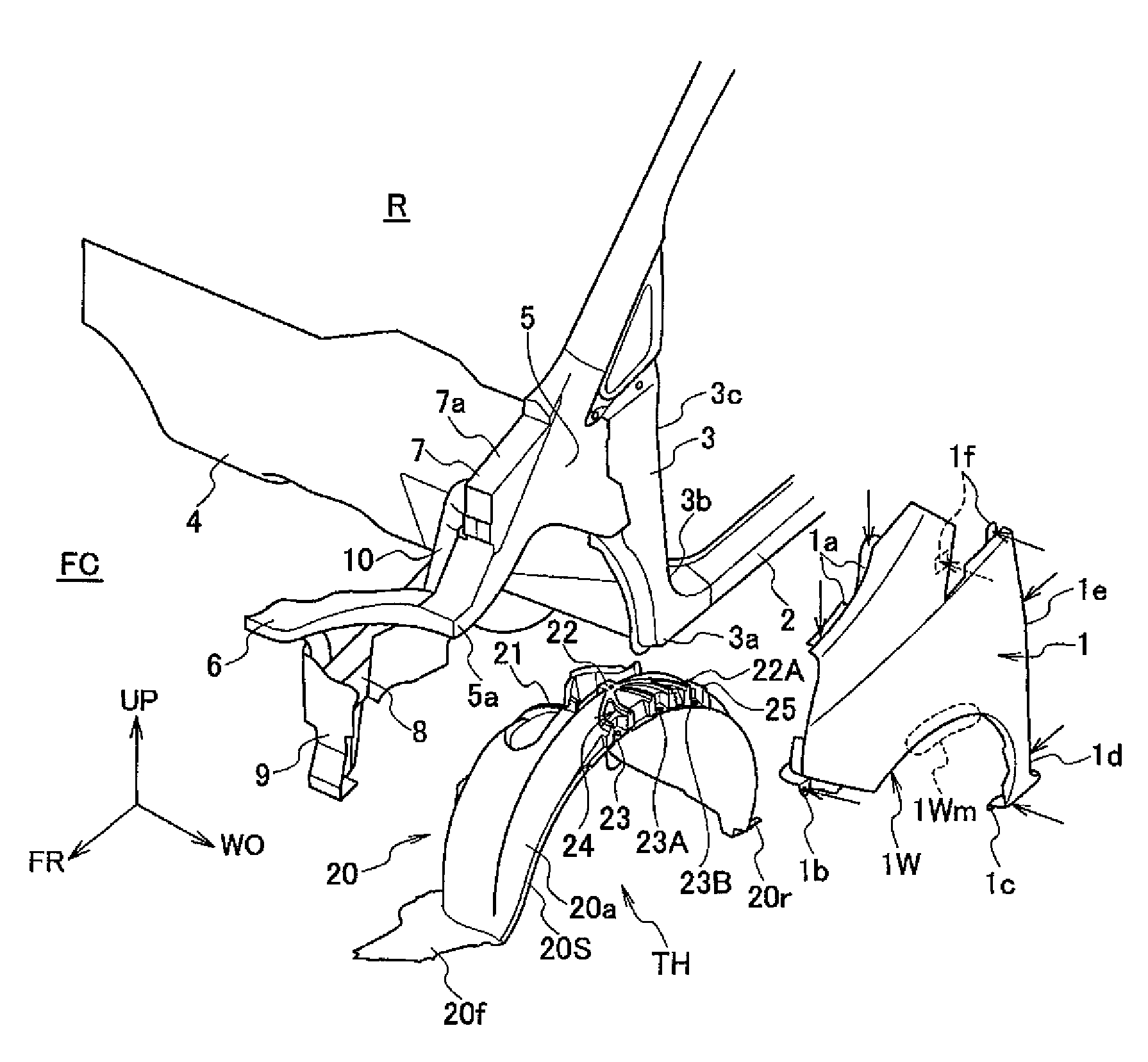
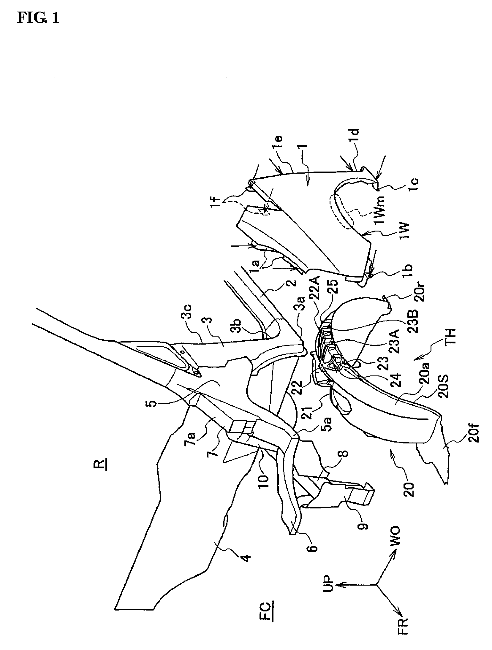
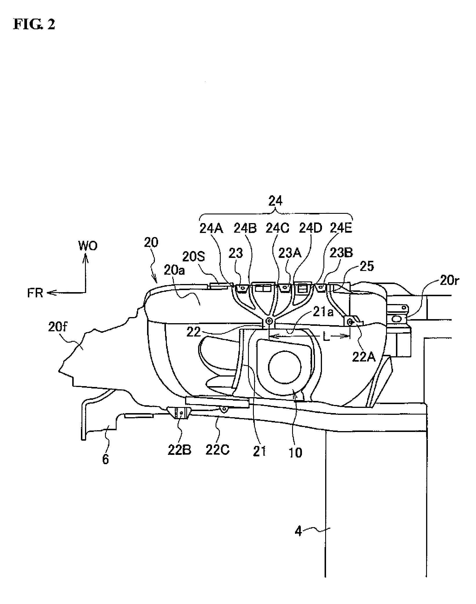
[0021]FIGS. 1 to 7 show a fender protector structure in accordance with embodiments of the present disclosure. FIG. 1 is an exploded perspective view of a port side of a vehicle body front portion including a fender protector structure. FIG. 2 is a bottom view of the fender protector structure. FIG. 3 is a top view of the fender protector. FIG. 4 is a perspective view of the fender protector when seen from the bottom. FIG. 5 is a perspective view of the fender protector when seen from an outer front side. FIG. 6 is a perspective view of the fender protector when seen from an outer rear side. FIG. 7 is a cross-sectional view taken along a line VII-VII in FIG. 3. Further, in each drawing, “FR” indicates a vehicular front direction, “UP” indicates a vehicular upward direction and “WO” indicates an outer side in a vehicular width direction.

[0022]As shown in FIG. 1, in a ve...


PUM

PropertyMeasurementUnit
shapeaaaaaaaaaa
rigidityaaaaaaaaaa
widthaaaaaaaaaa

Abstract

A fender protector structure of a vehicle which includes a body structure including a body panel and a fender panel. The body structure defines a wheel well. A fender protector is connected to the body structure for covering an outer periphery of the wheel well, and a reinforcing structure for the fender protector extends from the body panel to the fender panel, wherein the reinforcing structure includes fixing the fender protector to the body panel.

Description

CROSS-REFERENCE TO RELATED APPLICATIONS[0001]The present application claims priority from Japanese Patent Application No. 2007-324479, filed Dec. 17, 2007. The contents of the priority application are hereby incorporated by reference in their entirety.BACKGROUND OF THE DISCLOSURE[0002]1. Field of the Disclosure[0003]The present disclosure relates to a fender protector structure of a vehicle. More particularly, the present disclosure relates to a fender protector structure having a reinforcing beam portion extending between a body panel and a fender panel.[0004]2. Description of the Related Art[0005]Japanese Laid-Open Patent Publication No. (Hei) 11-208514 (hereinafter “Patent Document 1”) discloses a vehicle wherein a wheel arch portion is formed at a portion of a fender panel corresponding to a wheel well of a body structure, and wherein a fender protector is disposed on the fender panel so as to cover an outer side of a vehicle wheel well between the wheel arch portion of the fend...

Claims


Application Information

Patent Timeline
22 Mar 2011
Publication
US7909392B2
IPC
B62D25/16
CPC
B62D25/161; Y10T29/49826; B60R19/02; B62D25/18; B62D29/041
Inventors
TAKEUCHI, MAKOTO; NITO, HITOSHI