Knife and method of using same

a technology of knives and knives, which is applied in the field of knives, can solve the problems of time-consuming and tiring process, not so easy or efficient for amateurs, and achieve the effect of meat, reducing the cost of fish processing, and improving the quality of fish processing

Inactive Publication Date: 2011-03-22
WALTMAN JASON CRAIG
View PDF6 Cites 19 Cited by
  • Summary
  • Abstract
  • Description
  • Claims
  • Application Information

AI Technical Summary

Benefits of technology

The method of using this butterfly knife apparatus involves placing a piece of meat on a cutting surface, the meat having a first end, a second end a top and a bottom, hovering or placing the second blade over the top of the piece of meat to one side of the first end of the piece of meat by approximately the predetermined distance between the first and second knife blades and the first knife blade by a distance of approximately twice the predetermined distance from said one end of the piece...

Problems solved by technology

While this above mentioned, tried and true, technique works well for butchers and people with a lot of experience in the butterfly meat process, it is not so easy or efficient for amateurs who have never made a...

Method used


Image

  • Knife and method of using same
  • Knife and method of using same
  • Knife and method of using same

Examples


embodiment 10

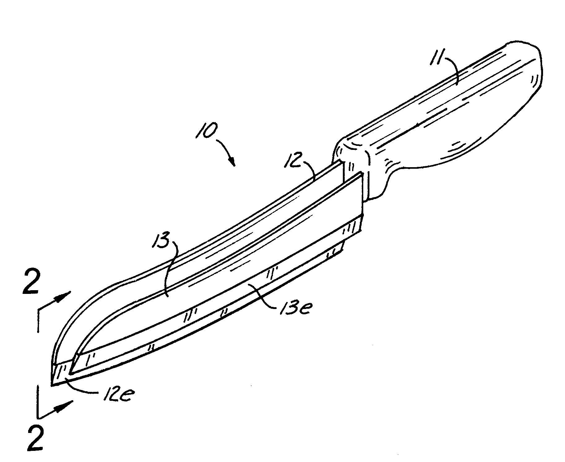
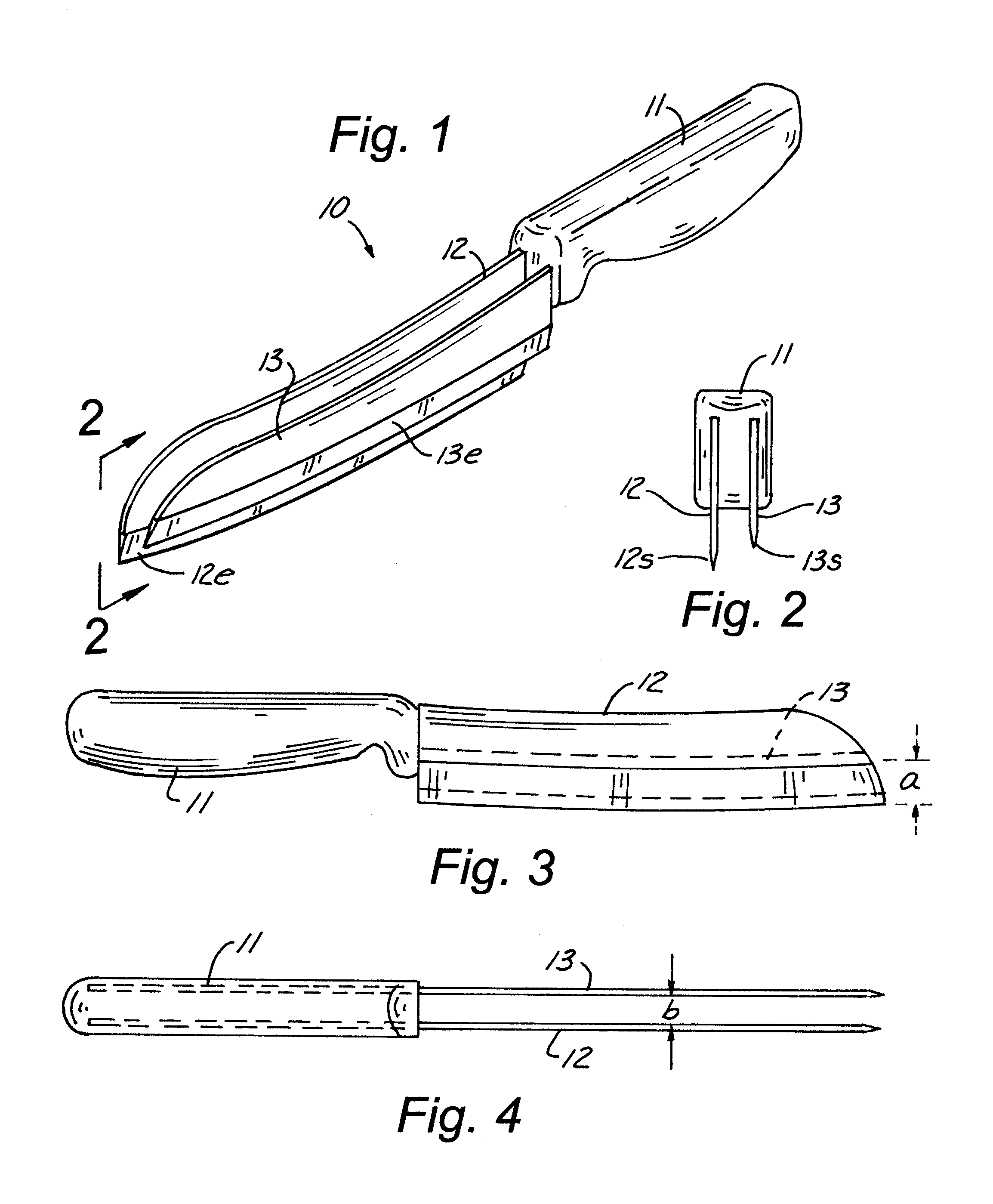
Referring now to the drawings, wherein like reference numerals designate identical or corresponding parts throughout the several views, FIG. 1 shows the present invention in a preferred embodiment 10, including a handle 11 with a first blade 12 permanently affixed to the handle 11 and a second blade 13 permanently affixed to the handle 11. The first blade 12 has a sharpened lower edge 12e and the second blade has a sharpened lower edge 13e.

Looking to FIGS. 2 and 3 it can be seen that the lower part of the sharpened lower edge 13e of the second blade 13 is spaced a distance “a” above the sharpened lower edge 12e of the first blade 12.

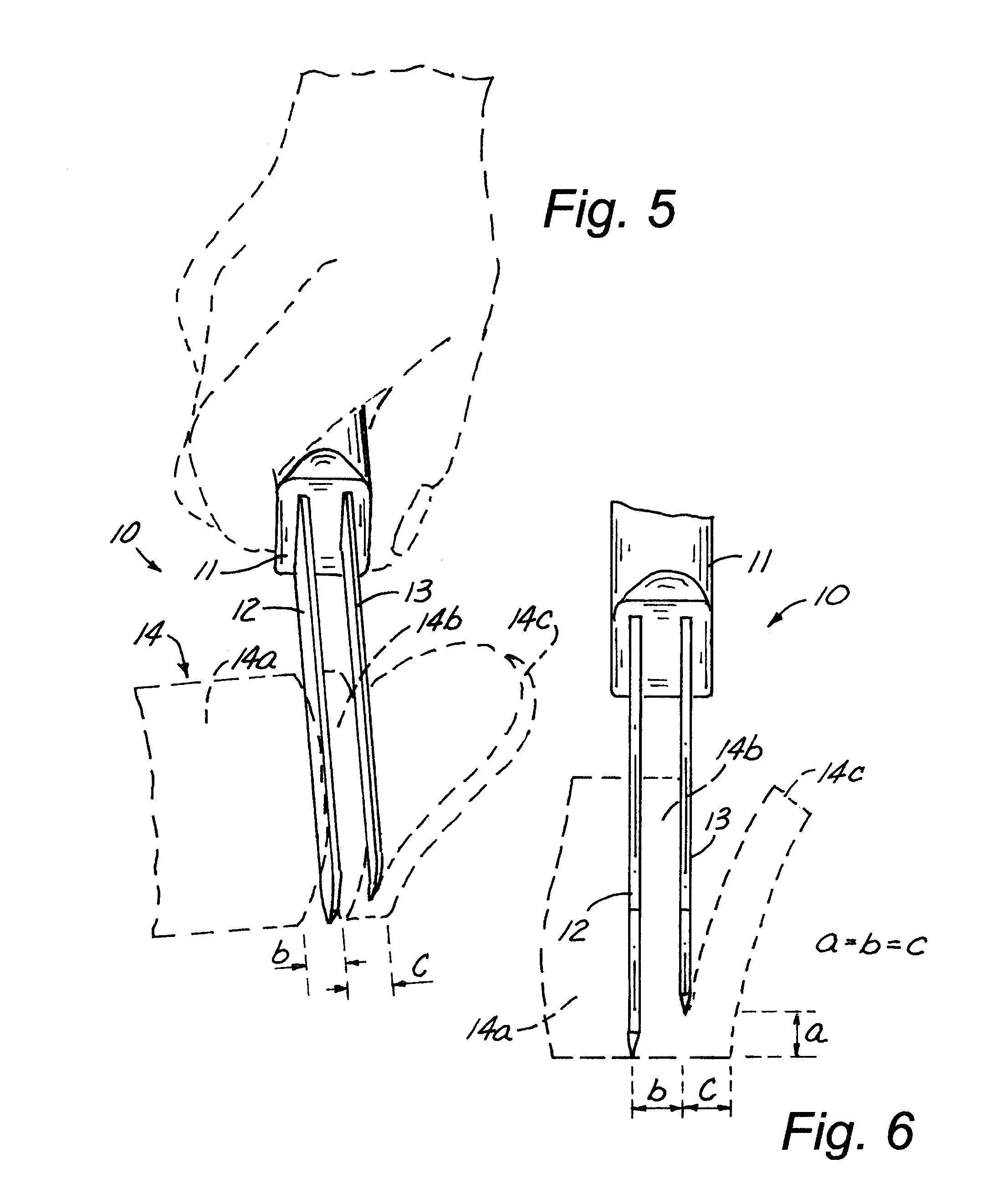
Looking to FIGS. 2 and 4 it can be seen that the second blade 13 is spaced from the first blade 12 is a distance “b”. While not drawn to scale in these figures, it is preferred, but not required, that the distance “a” be approximately the same as distance “b” for reasons given below.

Looking now to FIGS. 5 and 6, a method of using the preferred embodimen...

second embodiment

Looking now to FIGS. 7-11, the present invention is shown. Knife 110 has a handle 111 with a fixed blade 112, though blade 112 could be made to be removable like second blade 113 as will be explained below. The first blade 112, has a sharpened lower edge 112e and the second blade 113 has a lower sharpened edge 113e. The second blade 113 can be locked into or removed from any one of the slots 111a, 111b, or 111c shown in FIGS. 7 and 8.

A locking device 115 is shown in FIGS. 9-11 for selectively locking or releasing blade 113 in any one of the slots 111a, 111b or 111c. The locking device 115 has a button base member 115b with a helical compression spring 115s extending upwardly therefrom. Three spaced apart locking members 115a, 115b and 115c are rigidly attached to the button base member 115b. A pivot shaft 115p extends through each of the three spaced apart locking members 115a, 115b and 115c and extends into the handle 111 so that the locking device 115 can be moved from the locked ...

first embodiment

Once the knife 110 is in the configuration desired, for example such as shown in FIG. 7, then the procedure of using it is identical to that shown in FIGS. 5 and 6 of the first embodiment butterfly knife 10 as explained above.


PUM


Abstract

A knife for producing a butterfly cut of meat, the knife having a handle and a first knife blade attached at one end thereof to the handle, the first knife blade having a first distance between the top and the bottom thereof and being sharpened on the bottom thereof. A second knife blade is operatively attached at one end thereof to the handle, the second knife blade having a fixed position disposed generally parallel to the first knife blade, the second knife blade having being sharpened on the bottom thereof, the bottom of the second knife blade being disposed above and at a predetermined distance to one side of the bottom of the first knife blade over a major portion of the first and second knife blades when the second blade is attached to the handle in the fixed position thereof.

Description

BACKGROUND OF THE INVENTION1. Field of the InventionThe present invention relates generally to knives and more particularly to a knife for producing a “butterfly” cuts of meat such as a “butterfly chop”.2. Background ArtKnives have been used for centuries for cutting meat. One cut of meat called a “butterfly” cut is made by taking a slice of meat, such as a thick pork or beef tenderloin and cutting it like one would cut a bun for use to hold a hamburger, but not cutting the slice of meat all the way through. For example, if the piece of meat is two inches thick, then one might cut it through leaving one inch on the top and bottom and then cutting to within one inch of having cut it into two pieces. After that, one would fold it open and end up with one “butterfly” piece that is essentially one inch thick throughout its entire thickness. These cuts can be cooked flat, or stuffing can be added and the piece of “butterfly” meat can be refolded essentially to the configuration it had be...

Claims


Application Information

Patent Timeline
IPC IPC(8): A22C18/00
CPCA22C17/0033B26B3/04
Inventor WALTMAN, JASON CRAIG
Owner WALTMAN JASON CRAIG
Why Eureka
Try Eureka