Electro-conductive contact structure for enclosure sealing in housings

a contact structure and electro-conductive technology, applied in the field of enclosure sealing, can solve the problems of increasing size, shrinking and loss of elastomeric gaskets, and increasing the size of elastomeric gaskets

Inactive Publication Date: 2011-03-22
EXCELIS INC
View PDF15 Cites 12 Cited by
  • Summary
  • Abstract
  • Description
  • Claims
  • Application Information

AI Technical Summary

Benefits of technology

[0007]In accordance with a third aspect of the invention, an electro-conductive contact structure for sealing the interior of an enclosure from interference includes first and second electro-conductive contact surfaces. The first electro-conductive contact is surface includes a series of first fingers and plurality of pockets between the first fingers. The second electro-conductive contact surface includes a series of second fingers and a plurality of pockets between the second fingers. The first fingers are sized and arranged to fit in the pockets between the second fingers, and the second fingers are sized and arranged to fit in the pockets between the first fingers, so as to seal the interior of the enclosure from interference.

Problems solved by technology

Compliant gaskets and bridge connectors can create many problems.
For example, elastomeric gaskets shrink and lose their integrity over time.
When gaskets shrink, gaps form between the housing surfaces and increase in size, increasing the potential for EMI and RFI.
Gaskets and bridge connectors also make assembly more complicated, and affect the positioning and design of environmental gaskets and other elements that need to be included on the housing parts.
Although the gaps are relatively small, and are assumed to be insignificant, the gaps are still problematic for many applications.

Method used


Image

  • Electro-conductive contact structure for enclosure sealing in housings
  • Electro-conductive contact structure for enclosure sealing in housings
  • Electro-conductive contact structure for enclosure sealing in housings

Examples


Embodiment Construction

[0013]Although the invention is illustrated and described herein with reference to specific embodiments, the invention is not intended to be limited to the details shown. Various modifications may be made in the details within the scope and range of equivalents of the claims and without departing from the invention.

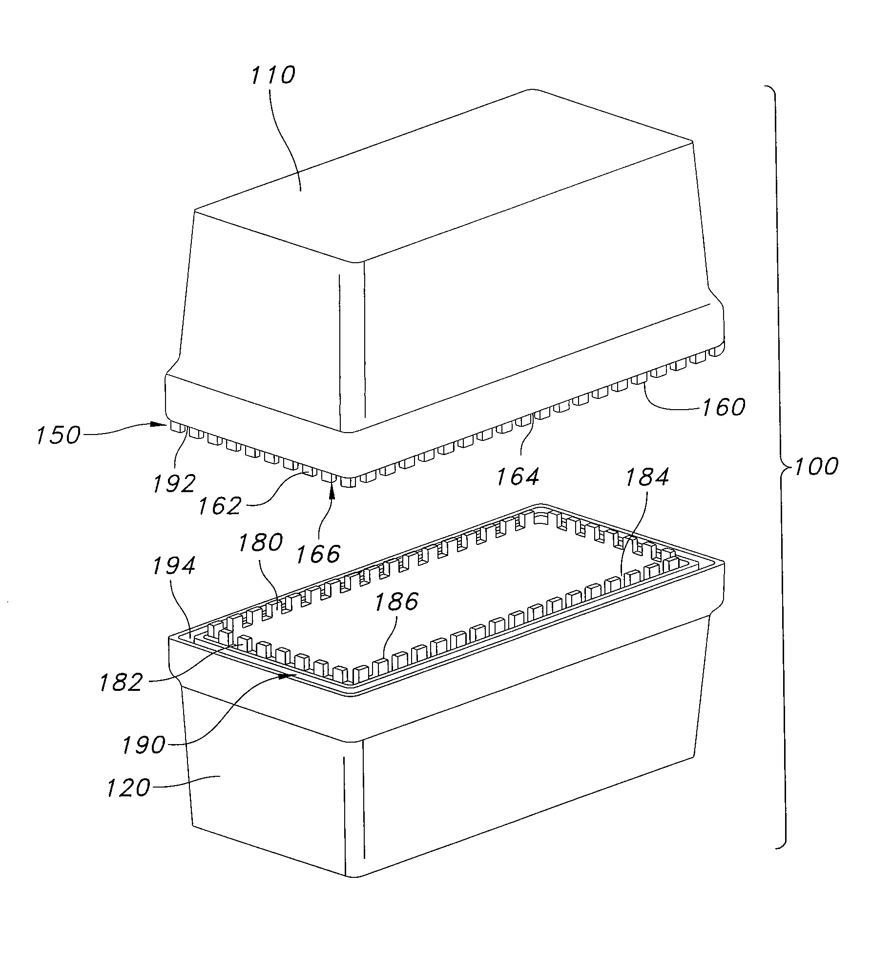
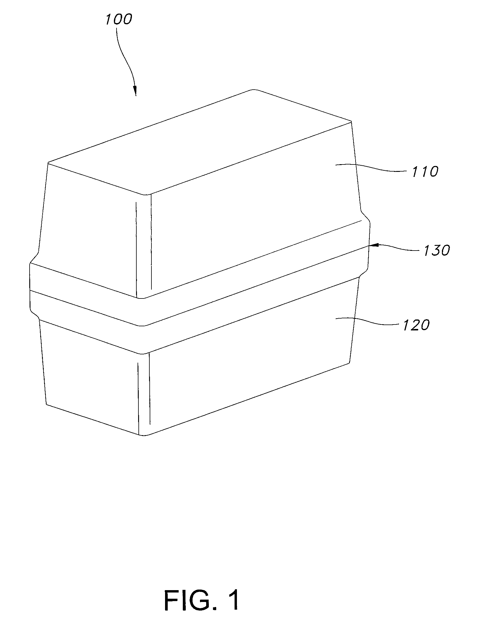
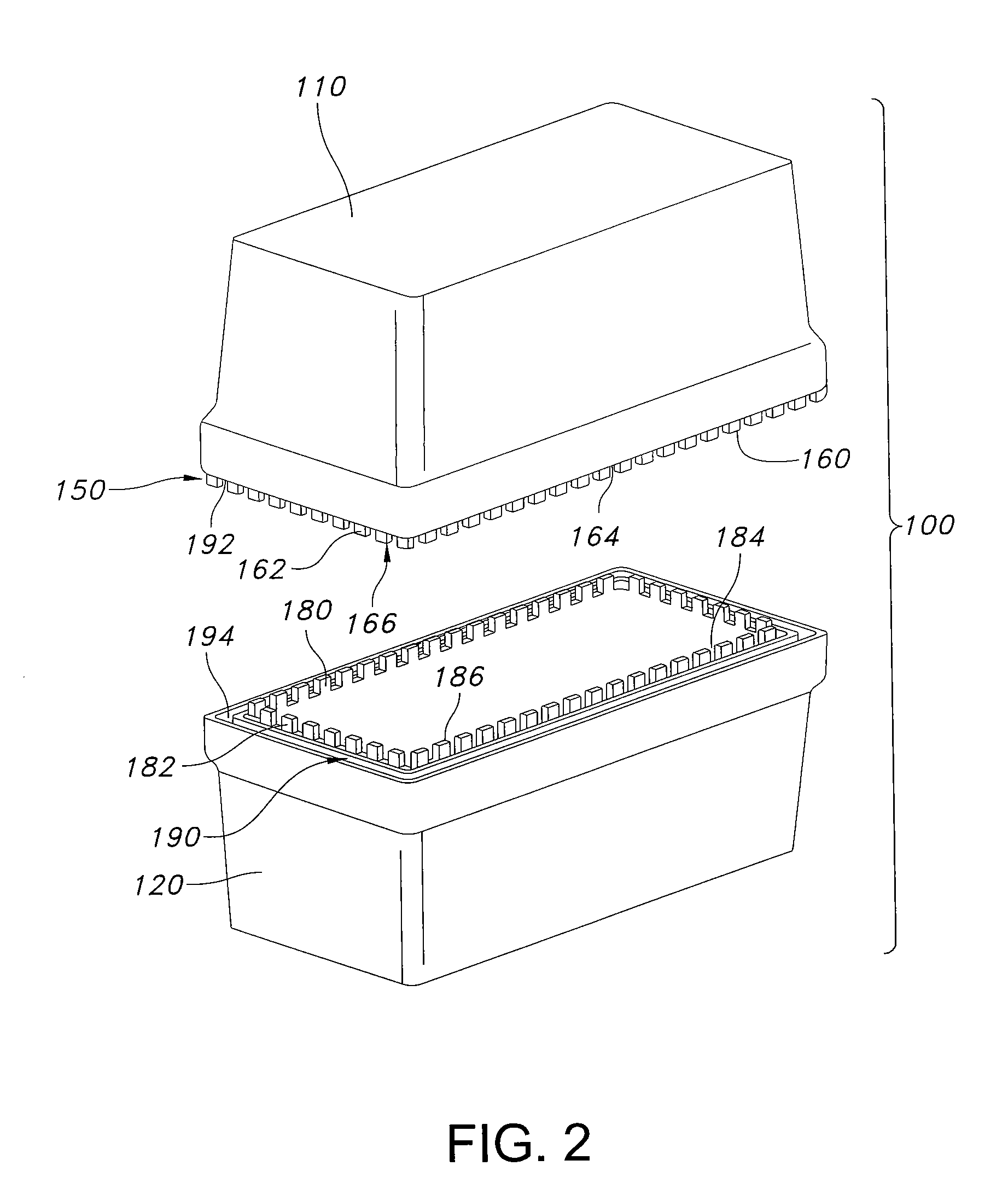
[0014]Housings in accordance with the invention resolve many of the drawbacks associated with conventional EMI and RFI shielding techniques. In preferred embodiments, the housings have an interleaved electro-conductive contact structure integrated in the housing. The contact structure is integrated in the design of the housing during manufacturing, such as by molding or machining the contact structure with the housing part. By integrating the contact structure into the design of the housing, there is complete freedom to design the contact structure when the housing is designed. The contact structure can be designed with configuration that is optimized to shield specific e...


PUM


Abstract

An electro-conductive contact structure for sealing the interior of an enclosure from interference includes first and second electro-conductive contact surfaces. In one embodiment, the first electro-conductive contact surface includes a plurality of projections, and the second electro-conductive contact surface includes a plurality of slots. The projections are configured for insertion into the slots to form an electro-conductive interface between the first and second portions of the enclosure. In another embodiment, the electro-conductive contact structures are formed on first and second housing parts, respectively. In another embodiment, the electro-conductive contact surfaces each include a series of fingers and a plurality of pockets between the fingers.

Description

FIELD OF THE INVENTION[0001]The present invention relates generally to housings, and more specifically to electro-conductive contact structures that are integrated into housings.BACKGROUND[0002]Various housing are used to protect electronic equipment from environmental conditions and disruptions caused by electromagnetic interference (EMI) or radio frequency interference (RFI). The housings typically have two or more housing parts that are joined together to create an enclosure. Seams or gaps between the housing parts can allow EMI and RFI to penetrate the housing. To prevent EMI and RFI, many housings have some form of compliant gasket or bridge connector connected across the gap or seam between the housing parts. The gasket or bridge, which is often a stocked part, facilitates electrical contact between the housing parts. Beryllium-copper finger stock gaskets are a common type of EMI shielding gasket.[0003]Compliant gaskets and bridge connectors can create many problems. For examp...

Claims


Application Information

Patent Timeline
Patent Type & Authority Patents(United States)
IPC IPC(8): H05K9/00
CPCH05K9/0009H05K5/065
Inventor LYNAM, JEFF RONALD
Owner EXCELIS INC
Why Eureka
Try Eureka