Identification system and method for mask and ventilator components

a technology of identification system and mask, applied in the direction of valves, mechanical devices, operating means/releasing devices, etc., can solve the problems of inability to recognise newer mask types, lack of future mask compatibility, and limited design of new masks and other ventilator system components

Inactive Publication Date: 2011-03-29
RESMED LTD
View PDF12 Cites 43 Cited by
  • Summary
  • Abstract
  • Description
  • Claims
  • Application Information

AI Technical Summary

Problems solved by technology

One limitation of the menu set up system is a lack of future mask compatibility.
However the flow generator does not recognise newer mask types, and these are selected by closest fit to the existing selection options.
As a result, the design of new masks and other ventilator system components is limited by the need to keep similar pressure-flow characteristics to a known mask or component type, and new technologies which have significantly different pressure-flow characteristics—or which have variability in characteristics—have not previously been able to be adopted due to non-compatibility with the flow generators.

Method used


Image

  • Identification system and method for mask and ventilator components
  • Identification system and method for mask and ventilator components
  • Identification system and method for mask and ventilator components

Examples


Embodiment Construction

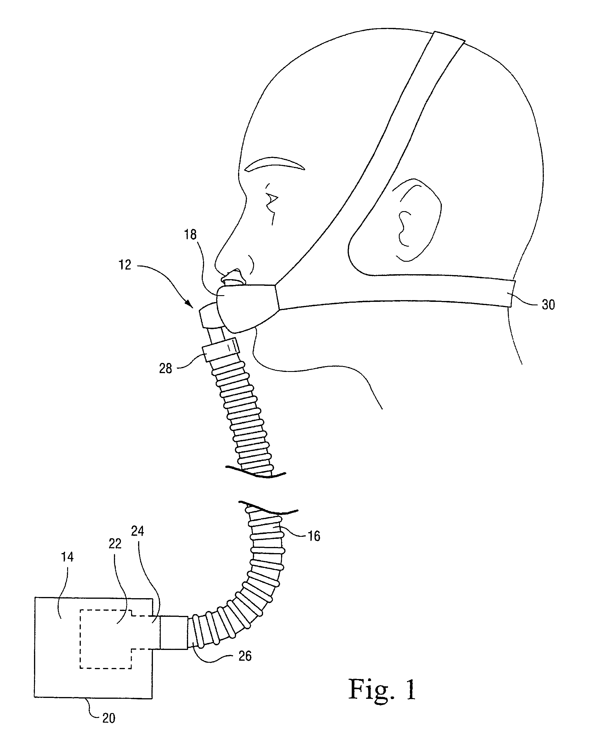
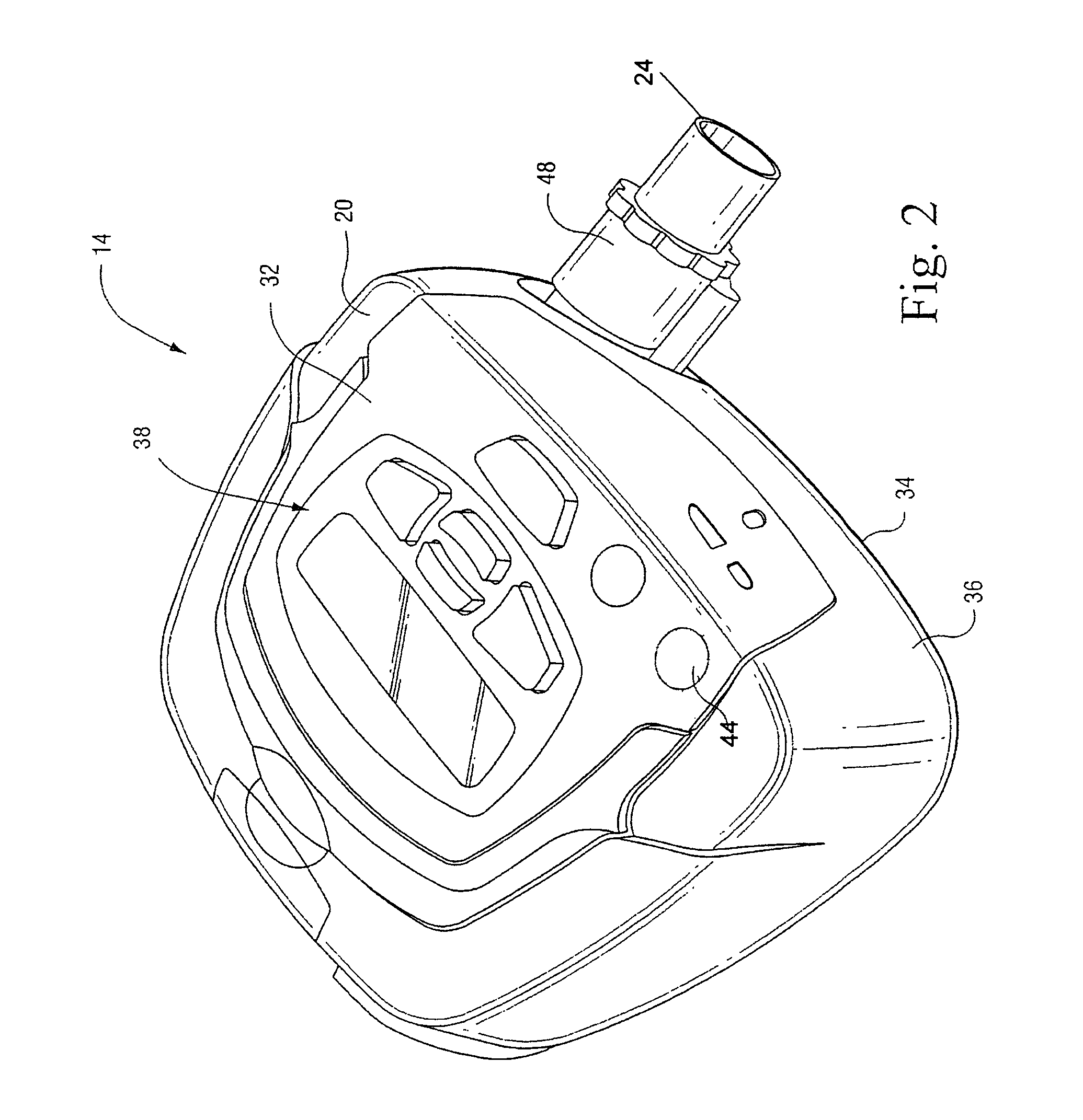
FIGS. 1 and 2 illustrate an apparatus 12 that delivers a supply of pressurized breathable air to a patient for treatment, e.g., of Sleep Disordered Breathing (SDB) with CPAP or Non-Invasive Positive Pressure Ventilation (NIPPV). As best shown in FIG. 1, the apparatus 12 generally includes a flow generator 14, an air delivery conduit 16, and a patient interface 18.

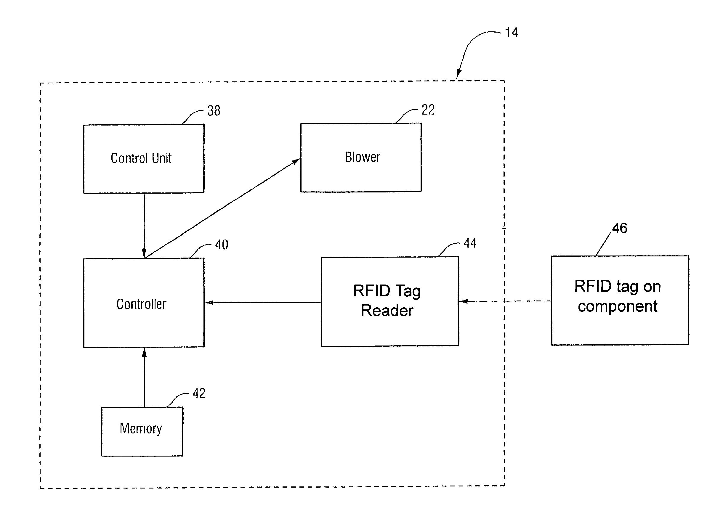
The flow generator 14 is structured to generate a supply of pressurized air to be provided to a patient for treatment. The flow generator 14 includes a housing 20 and a blower 22 supported within the housing 20. As is known in the art, the blower 22 is operable to draw a supply of air into the housing 20 through one or more intake openings and provide a pressurized flow of air at an outlet 24.

The supply of pressurized air is delivered to the patient via the air delivery conduit 16 that includes one end 26 coupled to the outlet 24 of the flow generator 14 and an opposite end 28 coupled to the patient interface 18, as shown i...


PUM


Abstract

Components of a CPAP or other patient ventilation apparatus have a remotely-readable identification tag encoded with component identification data. The flow generator controller 40 is programmed to receive data derived from the identification tag from a tag reader, and to adapt functions of the flow controller to coordinate with the component.

Description

CROSS REFERENCE TO PRIORITY APPLICATIONThis application claims the benefit of Australian Application No. 2005907200, filed Dec. 21, 2005, incorporated herein by reference in its entirety.BACKGROUND OF THE INVENTION1. Field of the InventionThe present invention relates to an apparatus that delivers breathable gas to a patient, and to methods for coordinating breathable gas delivery to ventilator system components being used.2. Description of Related ArtApparatus to deliver breathable gas to a patient typically includes a flow generator, an air delivery conduit, and a patient interface. Prior to use, operating parameters of the flow generator, e.g., treatment pressure, need to be manually adjusted by the patient to coordinate with the peripheral components, e.g., patient interface, being used. For example, known flow generators include a menu system that allows the patient to select the type of peripheral components being used, e.g., by brand, method of delivery, etc. Once the compone...

Claims


Application Information

Patent Timeline
Patent Type & Authority Patents(United States)
IPC IPC(8): A61M11/00
CPCA61M16/00A61M2205/3561A61M2205/6054A61M2205/6018A61M2205/3584A61M16/024A61M16/0066A61M16/0666A61M16/1055A61M2205/27A61M2205/52
Inventor HENRY, ROBERT EDWARDSELVARAJAN, KARTHIKEYANKWOK, PHILIP RODNEYGUNNING, PHILIP JOHNOATES, JOHN DAVID
Owner RESMED LTD
Why Eureka
Try Eureka