Robot cleaner having function for detecting separation of dust tank and control method thereof
a robot cleaner and dust tank technology, applied in the field of robot cleaners, can solve problems such as inconvenience for users
- Summary
- Abstract
- Description
- Claims
- Application Information
AI Technical Summary
Benefits of technology
Problems solved by technology
Method used
Image
Examples
first embodiment
[0043]Hereinafter, a robot cleaner according to the present invention will be explained.
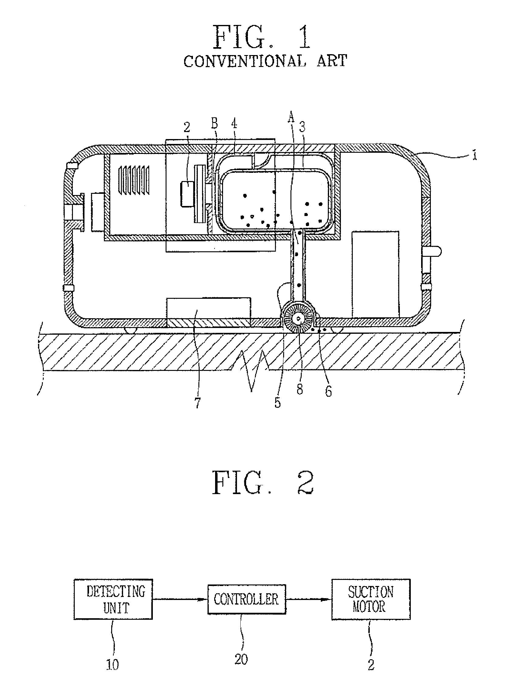
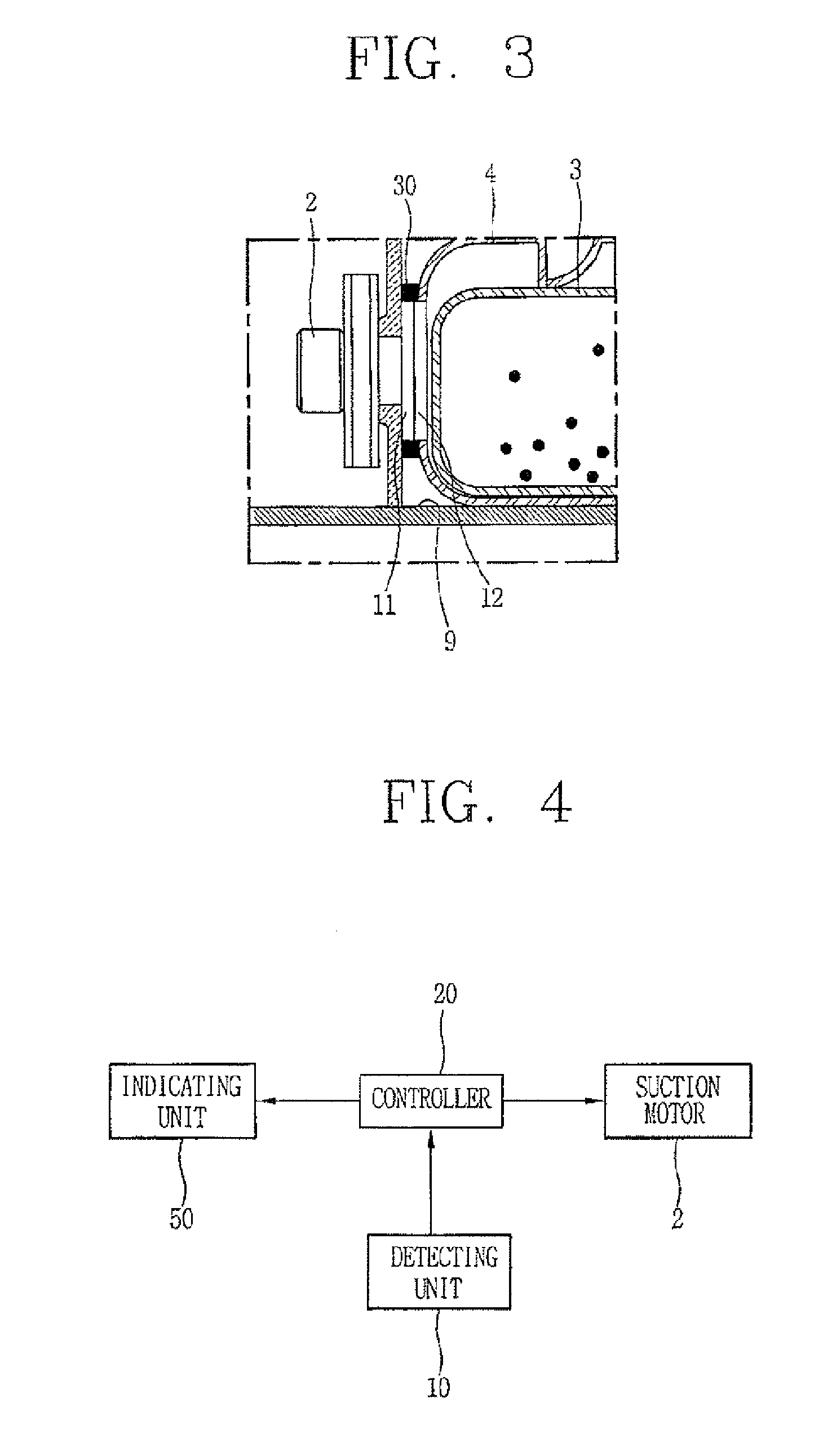
[0044]FIG. 2 is a block diagram showing a construction of a robot cleaner according to the present invention, and FIG. 3 is an enlarged sectional view showing a robot cleaner according to a first embodiment of the present invention.
[0045]As shown, a robot cleaner according to a first embodiment of the present invention comprises: a body 1 having a receiving portion 9 for mounting a dust tank 4; a detecting unit 10 installed at the receiving portion 9, for detecting whether the dust tank 4 has been separated from the body 1 by an interaction with the dust tank 4; and a controller 20 for controlling a suction motor 2 installed in the body 1 according to a detection result.
[0046]The detecting unit 10 is implemented as a magnetic sensor for immediately detecting whether the dust tank 4 has been separated from the body 1 by whether a line of magnetic force generated from a magnet portion provided at t...
second embodiment
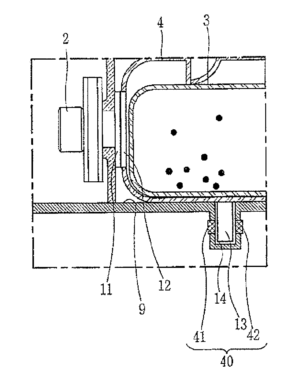
[0061]As shown, the detecting unit 10 of the robot cleaner according to the present invention consists of an infrared sensor 40 having a light emitting portion 41 for emitting infrared rays, and a light receiving portion 42 for receiving infrared rays. Whether the dust tank 4 has been separated from the receiving portion 9 is detected by whether the light receiving portion 42 has absorbed infrared rays.
[0062]At least one coupling protrusion 13 is protruding from a lower surface of the dust tank 4, and an insertion groove 14 for inserting the coupling protrusion 13 is formed at the receiving portion 9 of the body 1 in correspondence with the coupling protrusion 13. The infrared sensor 40 is installed in the insertion groove 14.
[0063]FIG. 5A shows a state that the light emitting portion 41 and the light receiving portion 42 of the infrared sensor 40 are mounted to face each other with the coupling protrusion 13 being interposed therebetween.
[0064]When the coupling protrusion 13 is ins...
third embodiment
[0072]The robot cleaner according to the present invention comprises a body 90; a dust tank 104 coupled to a receiving portion 100 concaved outside the body 90; and a detecting unit 10 installed at the receiving portion 100 for detecting whether the dust tank 104 has been separated from the receiving portion 100 by an interaction with the dust tank 104.
[0073]The robot cleaner according to the third embodiment of the present invention is different from the robot cleaners according to the first embodiment and the second embodiment in that the dust tank 104 is installed outside the body 90.
[0074]The receiving portion 100 consists of a horizontal contact portion 101 contacting a lower surface of the dust tank 104 under a state that the dust tank 104 is coupled to the receiving portion 100; and a vertical contact portion 102 arranged to be perpendicular to the horizontal contact portion 101, and contacting both side surfaces and a front surface of the dust tank 104 under a state that the...
PUM
| Property | Measurement | Unit |
|---|---|---|
| area | aaaaa | aaaaa |
| suction force | aaaaa | aaaaa |
| pressure | aaaaa | aaaaa |
Abstract
Description
Claims
Application Information
 - R&D
- Intellectual Property
- Life Sciences
- Materials
- Tech Scout
- Unparalleled Data Quality
- Higher Quality Content
- 60% Fewer Hallucinations
Browse by: Latest US Patents, China's latest patents, Technical Efficacy Thesaurus, Application Domain, Technology Topic, Popular Technical Reports.
© 2025 PatSnap. All rights reserved.Legal|Privacy policy|Modern Slavery Act Transparency Statement|Sitemap|About US| Contact US: help@patsnap.com


