Robot cleaner having function for detecting separation of dust tank and control method thereof

a robot cleaner and dust tank technology, applied in the field of robot cleaners, can solve problems such as inconvenience for users

Inactive Publication Date: 2007-02-22
LG ELECTRONICS INC
View PDF7 Cites 20 Cited by
  • Summary
  • Abstract
  • Description
  • Claims
  • Application Information

AI Technical Summary

Benefits of technology

[0011] Therefore, an object of the present invention is to provide a robot cleaner that is not op...

Problems solved by technology

Moreover, when the dust tank is mounted inside the body, certifying whether the du...

Method used


Image

  • Robot cleaner having function for detecting separation of dust tank and control method thereof
  • Robot cleaner having function for detecting separation of dust tank and control method thereof
  • Robot cleaner having function for detecting separation of dust tank and control method thereof

Examples


first embodiment

[0043] Hereinafter, a robot cleaner according to the present invention will be explained.

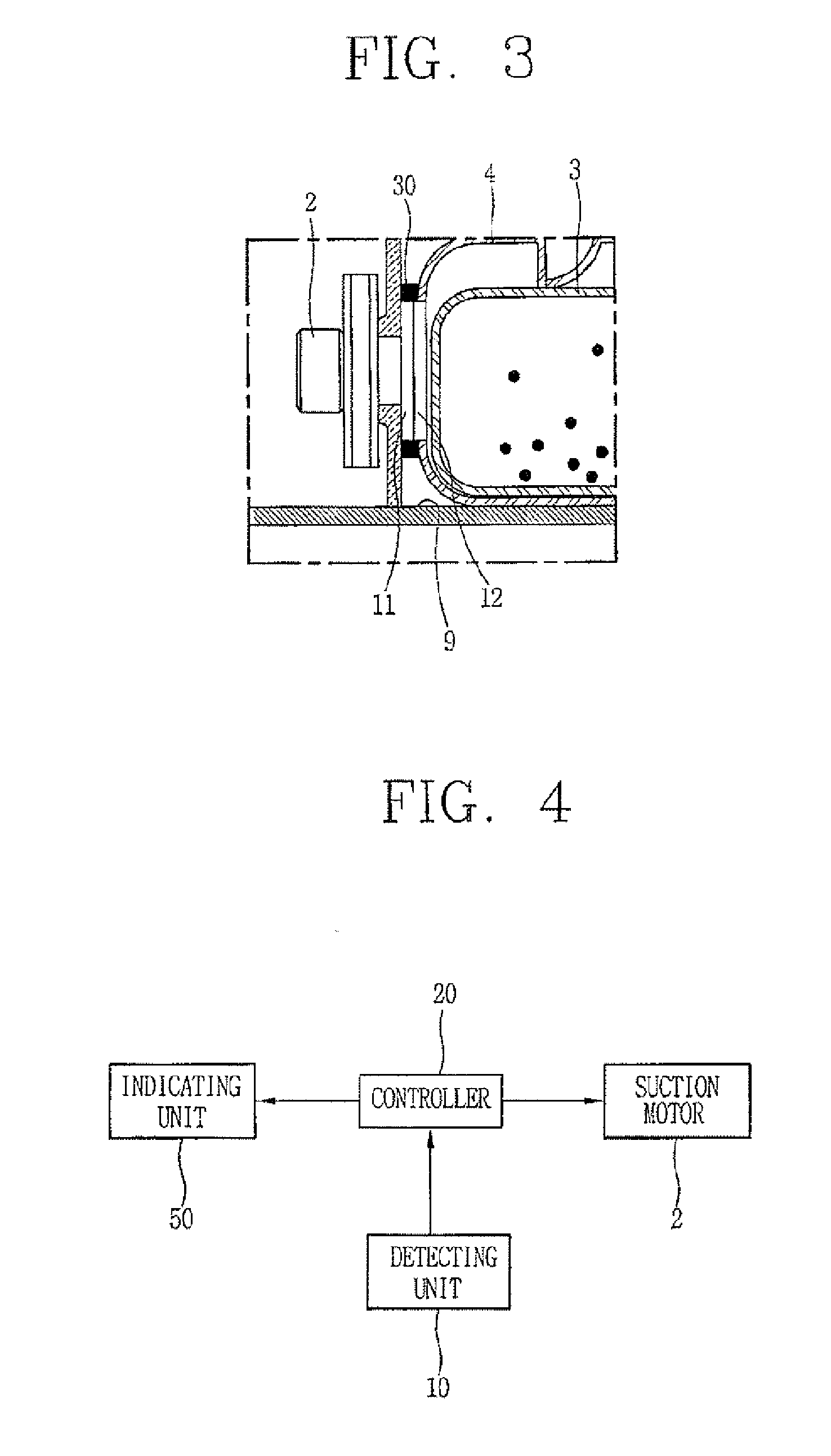
[0044]FIG. 2 is a block diagram showing a construction of a robot cleaner according to the present invention, and FIG. 3 is an enlarged sectional view showing a robot cleaner according to a first embodiment of the present invention.

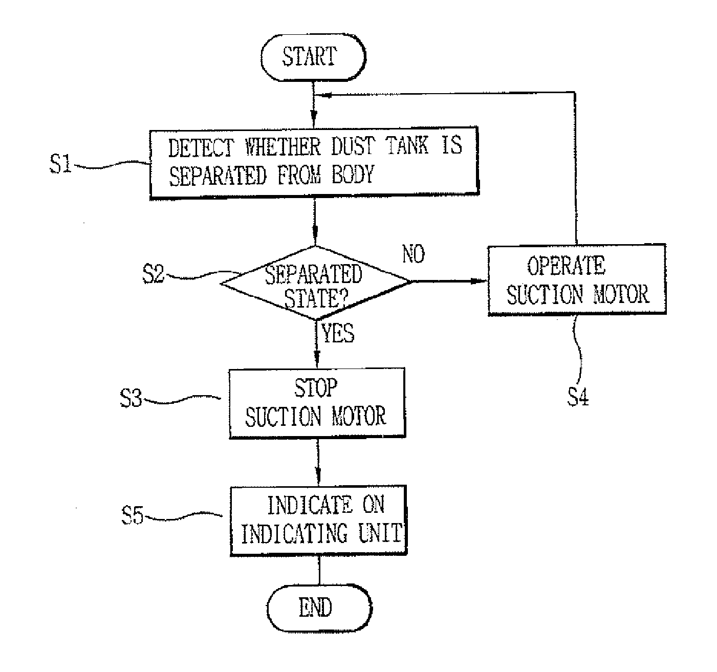
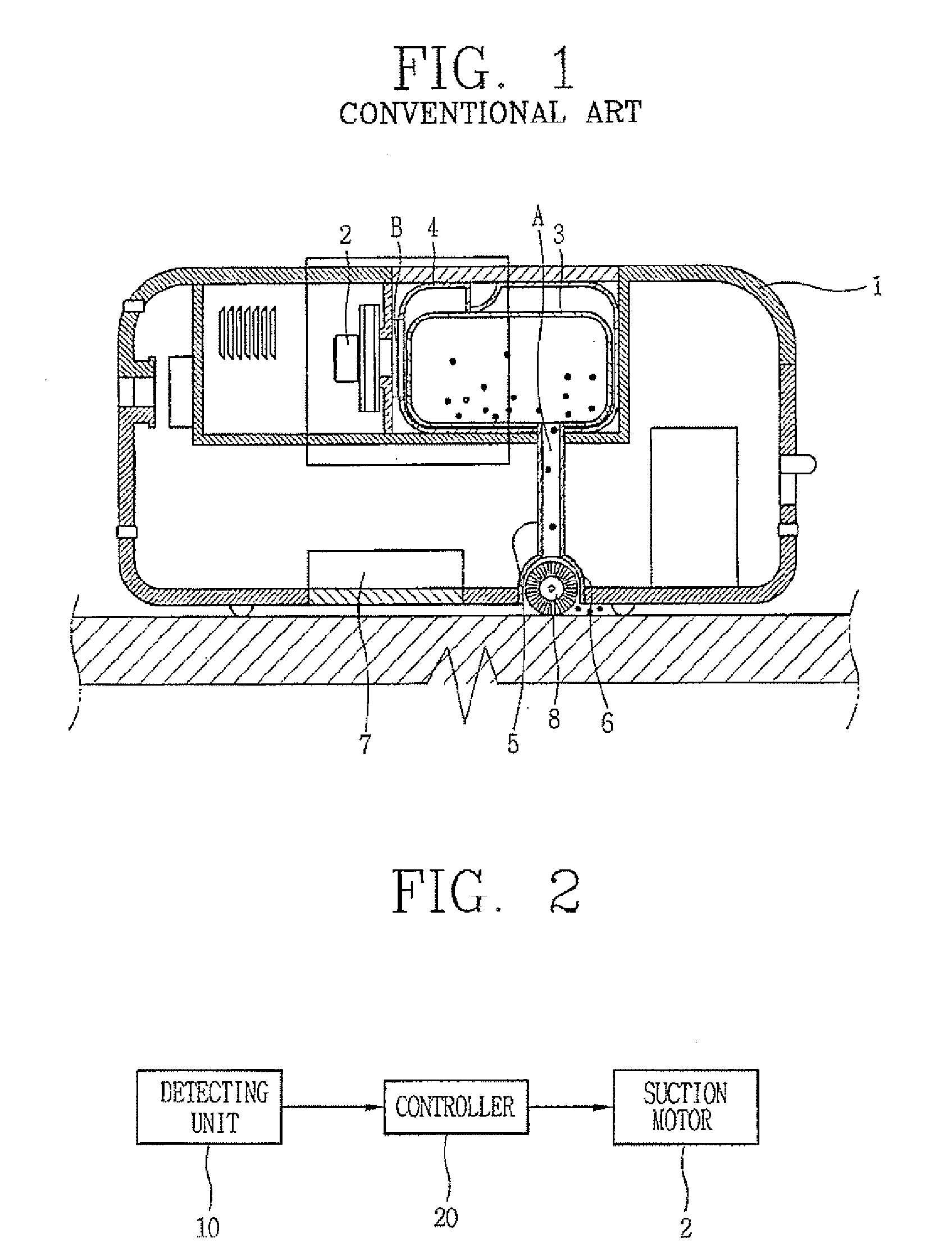
[0045] As shown, a robot cleaner according to a first embodiment of the present invention comprises: a body 1 having a receiving portion 9 for mounting a dust tank 3; a detecting unit 10 installed at the receiving portion 9, for detecting whether the dust tank 3 has been separated from the body 1 by an interaction with the dust tank 3; and a controller 20 for controlling a suction motor installed in the body 1 according to a detection result.

[0046] The detecting unit 10 is implemented as a magnetic sensor for immediately detecting whether the dust tank 3 has been separated from the body 1 by whether a line of magnetic force generated from a magnet portion provided a...

second embodiment

[0061] As shown, the detecting unit 10 of the robot cleaner according to the present consists of an infrared sensor 40 having a light emitting portion 41 for emitting infrared rays, and a light receiving portion 42 for receiving infrared rays. Whether the dust tank 3 has been separated from the receiving portion 9 is detected by whether the light receiving portion 42 has absorbed infrared rays.

[0062] At least one coupling protrusion 13 is protruding from a lower surface of the dust tank 3, and an insertion groove 14 for inserting the coupling protrusion 13 is formed at the receiving portion 9 of the body 1 in correspondence with the coupling protrusion 13. The infrared sensor 40 is installed in the insertion groove 14.

[0063]FIG. 5A shows a state that the light emitting portion 41 and the light receiving portion 42 of the infrared sensor 40 are mounted to face each other with the coupling portion 13 being interposed therebetween.

[0064] When the coupling portion 13 is inserted into ...

third embodiment

[0072] The robot cleaner according to the present invention comprises a body 90; a dust tank 104 coupled to a receiving portion 100 concaved outside the body 90; and a detecting unit 10 installed at the receiving portion 100 for detecting whether the dust tank 104 has been separated from the receiving portion 100 by an interaction with the dust tank 104.

[0073] The robot cleaner according to the third embodiment of the present invention is different from the robot cleaners according to the first embodiment and the second embodiment in that the dust tank 104 is installed outside the body 90.

[0074] The receiving portion 100 consists of a horizontal contact portion 101 contacting a lower surface of the dust 104 under a state that the dust tank 104 is coupled to the receiving portion 100; and a vertical contact portion 102 arranged to be perpendicular to the horizontal contact portion 101, and contacting both side surfaces and a front surface of the dust tank 104 under a state that the ...


PUM


Abstract

A robot cleaner comprises: a body having a receiving portion for mounting a dust tank; a detecting unit installed at the receiving portion, for detecting whether the dust tank has been separated from the body by an interaction with the dust tank; and a controller for controlling a suction motor installed in the body according to a detection result. When the dust tank is separated from the receiving portion, the detecting unit detects the separated state of the dust tank immediately thus to stop the suction motor. Accordingly, dust is prevented from being introduced into the body.

Description

RELATED APPLICATION [0001] The present disclosure relates to subject matter contained in priority Korean Application No. 10-2005-0073507, filed on Aug. 10, 2005, which is herein expressly incorporated by reference in its entirety. BACKGROUND OF THE INVENTION [0002] 1. Field of the Invention [0003] The present invention relates to a robot cleaner, and more particularly, to a robot cleaner having a function for detecting separation of a dust tank from a body, and operated only when the dust tank is mounted at the body. [0004] 2. Description of the Background Art [0005] Generally, a robot cleaner serves to automatically clean an area to be cleaned by moving the area to be cleaned without a user's adjustment, and by sucking foreign materials such as dust, etc. from the floor surface. [0006] The related art robot cleaner will be explained with reference to FIG. 1. [0007] As shown, the related art robot cleaner comprises a suction motor 2 installed in a body 1 for generating a suction for...

Claims


Application Information

Patent Timeline
IPC IPC(8): B01D46/00
CPCA47L9/1472A47L9/2805A47L9/2842A47L2201/06A47L9/2889A47L9/2894A47L2201/00A47L9/2857A47L9/28A47L11/00A47L9/00
Inventor BAEK, OH-HYUNIM, HYOUNG-DEUK
Owner LG ELECTRONICS INC
Why Eureka
Try Eureka