
Simulated firearm

a technology of simulated firearms and firearms, applied in the field of simulated firearms, can solve the problems of unrealistic effect of simulated gunfire, blank cartridges cannot be fed through a magazine, and cannot be ejected in a realistic manner,

Inactive Publication Date: 2011-04-19
DUCASTEL JR CHARLES J
View PDF22 Cites 6 Cited by
  • Summary
  • Abstract
  • Description
  • Claims
  • Application Information

AI Technical Summary

Benefits of technology

"The present invention is a simulated firearm that can only use blank cartridges. It has a chamber positioned at the front of the firearm that prevents the use of lethal cartridges or the discharge of projectiles. The technical effect of this invention is to provide a safer and more realistic training tool for firearms."

Problems solved by technology

One disadvantage with the squib explosive charge device is that the report and flash are not generated through the muzzle of the simulated firearm.
This makes the effect of the simulated gunfire unrealistic.
Another disadvantage is that blank cartridges cannot be fed through a magazine nor ejected in a realistic manner.
Since squib explosive charges are not contained in a detachable magazine, this device cannot be reloaded like a conventional firearm.
The disadvantage with this approach is that the flash and report are not realistically generated from the muzzle.
Actual firearms can be modified to use blank cartridges without discharging lethal projectiles, but there significant problems with this practice.
Unmodified actual firearms can be loaded inadvertently with lethal ammunition and cause unintended damage and serious injury.
Such projectiles have caused serious injury and death.
A further problem with discharging blanks from actual automatic firearms is that blank cartridges typically fail to generate sufficient gas pressure and / or recoil to cycle the action.
As firearms, actual firearms are subject to extensive legal restrictions governing their sale, possession, and use.
External modifications detract from the realistic appearance of simulated or actual firearms firearm.
In most types of adapters, the inadvertent discharge of a lethal cartridge will likely damage the adapter and firearm.
Any projectile, whether from a lethal cartridge or a detached portion of a blank cartridge, may cause result in death or serious injury.

Method used


Image

  • Simulated firearm
  • Simulated firearm
  • Simulated firearm

Examples


Embodiment Construction

FIGS. 1-9

Operation—FIGS. 1-9

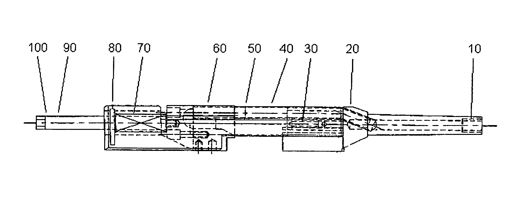
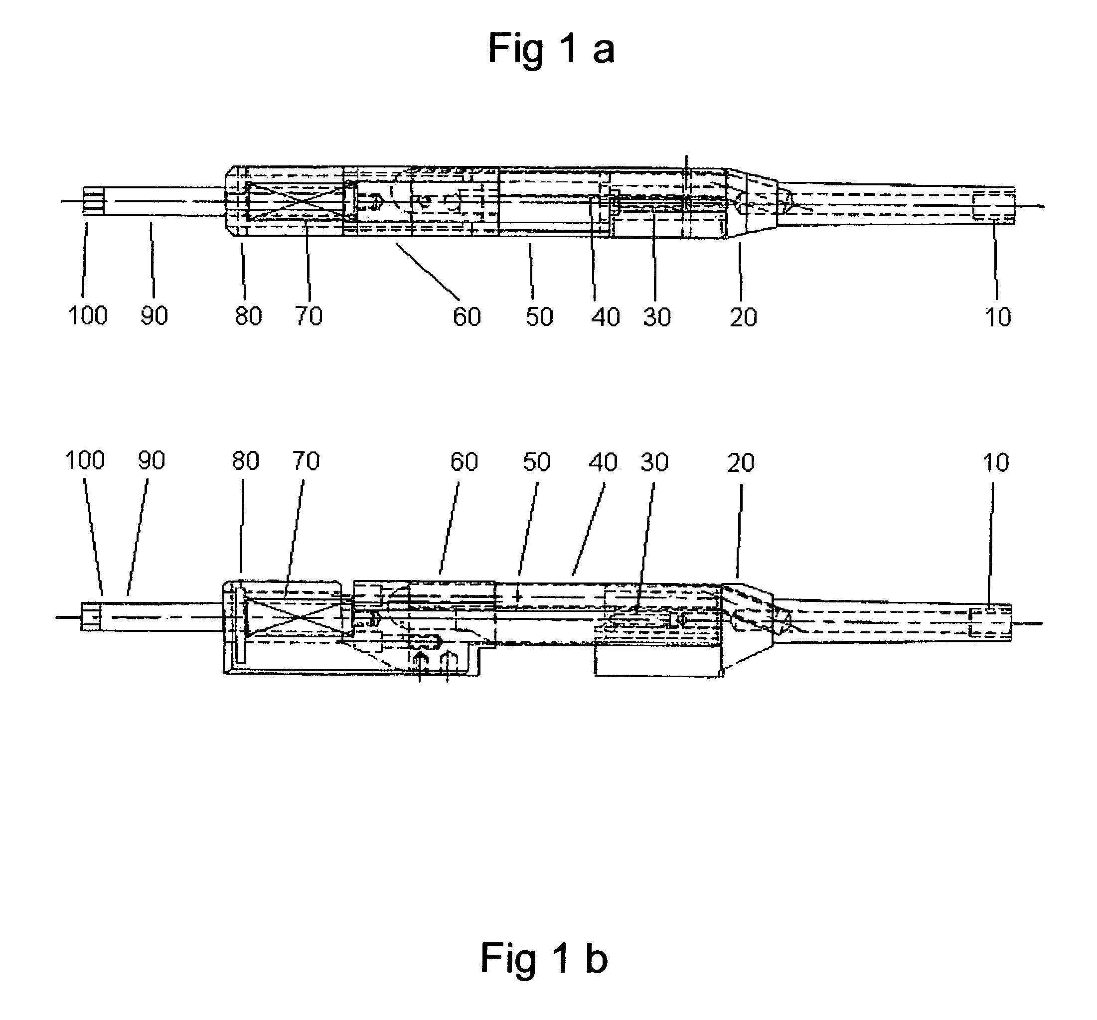
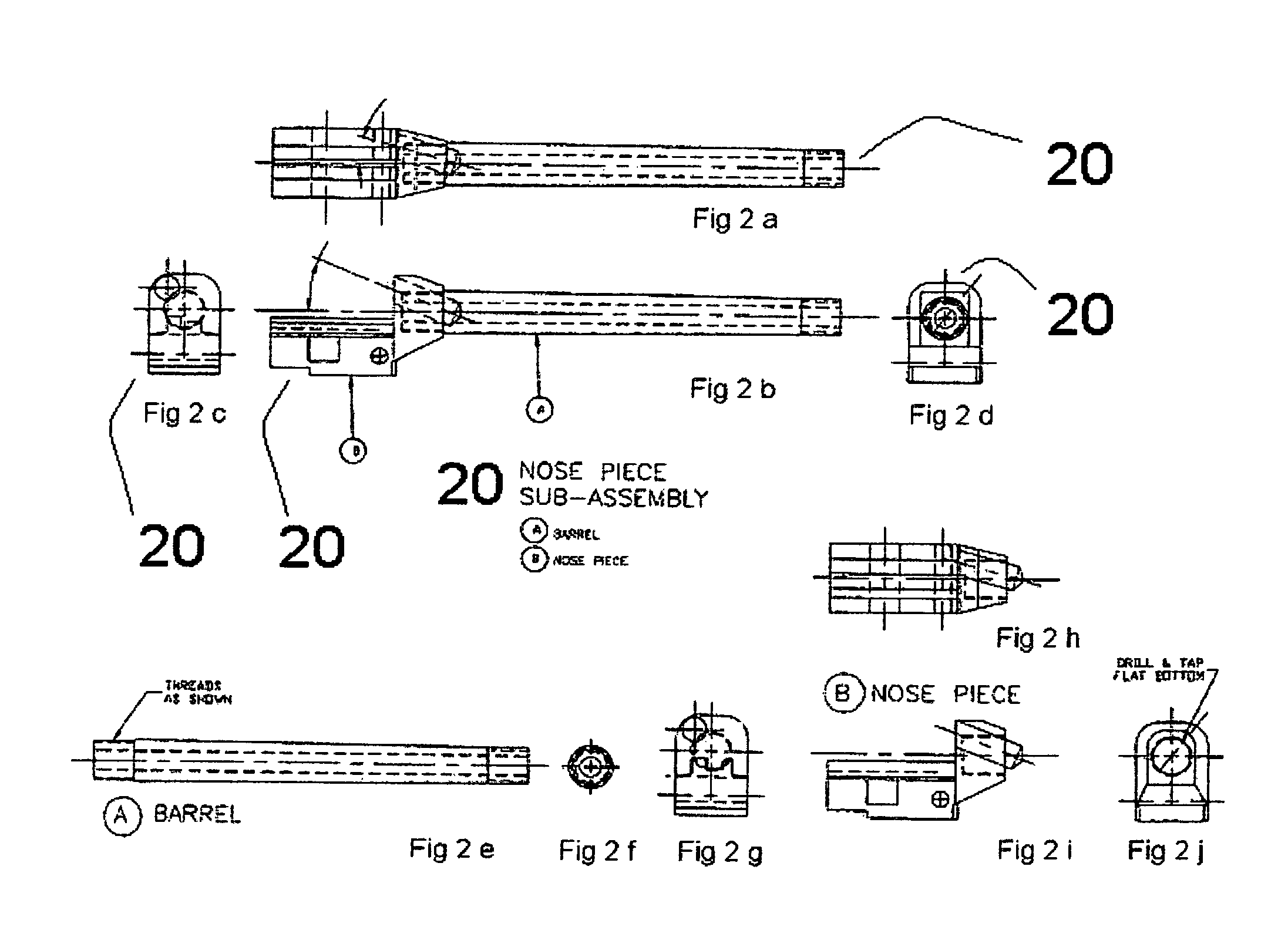
FIG. 1a and FIG. 1b show cross-sectional views of an embodiment of an automatic simulated firearm constructed in accordance with the present invention. The embodiment of the body 100 shown by FIGS. 1a and 1b externally resembles the PPSh-41 submachine gun. A set screw 10 of the simulated firearm is threadably attached to the barrel portion of the nose piece assembly 20. The nose piece sub-assembly 20 is attached to the body 100. The gas tube 40 extends from the nose piece sub-assembly 20 to the chamber block 60. A cavity extends from the U-shaped cavity of the chamber block 60 through gas tube 40 and to the cavity of the nose piece sub-assembly 20. The slide 50 is slidably attached to the body 100, and travels between the nose piece sub-assembly 20 and the chamber block 60. The slide 50 houses the firing pin 30. The forward section of the spring guide 90 is circumferentially mounted by the operating spring 70. The operating spring 70 is limited in its rea...


PUM


Abstract

A simulated firearm for discharging a blank cartridge and generating a realistic flash and report from the muzzle. The simulated firearm of the present invention prevents the discharge of lethal cartridges or projectiles. The simulated firearm has a chamber 65. The chamber 65 is reversed so that the entrance to the chamber 65 faces the forward section of the simulated firearm. A blank cartridge is loaded into the chamber 65. The blank cartridge is safely discharged from the reversed chamber.

Description

FEDERALLY SPONSORED RESEARCHNot applicable.SEQUENCE LISTING OR PROGRAMNot applicable.BACKGROUND OF THE INVENTION1. Field of InventionThis application generally relates to simulated firearms, specifically to simulated firearms which use blank cartridges.2. Prior ArtSimulated firearms are safer substitutes of actual firearms for training, educational, recreational, and theatrical purposes. Simulated firearms resemble actual firearms and produce the realistic sound and visual effects of gunfire, without discharging lethal projectiles. Automatic simulated firearms are simulated firearms which generate the effects of gunfire in a repetitive manner.There are several types of known simulated firearms. One type disclosed by U.S. Pat. No. 5,233,776 discharges squib explosive charges along the forward section of the simulated firearm. This device can operate as an automatic simulated firearm by employing multiple squib explosive charges. One disadvantage with the squib explosive charge device...

Claims


Application Information

Patent Timeline
Patent Type & Authority Patents(United States)
IPC IPC(8): F41A21/10
CPCF41A9/46F41A33/00F41A21/26F41A21/12
Inventor DUCASTEL, JR., CHARLES J.
Owner DUCASTEL JR CHARLES J
Learn More