Inflation nozzle with valve-locating probe and pulsating air supply

a technology of pulsating air supply and inflation nozzle, which is applied in the direction of functional valve types, transportation and packaging, paper/cardboard articles, etc., can solve the problems of difficult to locate and open the aperture, and achieve the effect of quick and easy inflation

Active Publication Date: 2011-04-19
PREGIS INNOVATIVE PACKAGING
View PDF20 Cites 22 Cited by
  • Summary
  • Abstract
  • Description
  • Claims
  • Application Information

AI Technical Summary

Benefits of technology

[0007]The channel outlet is preferably configured to direct the expelled fluid along a longitudinal axis that is parallel to the channel. The nozzle body preferably has an exterior engagement surface configured for reception within and contact with the aperture of the flexible structure for directing fluid therein. In one embodiment, the diameter of the engagement surface at its widest point is between about ¼ and ⅓ inches. The nozzle body can also include ribs that protrude radially therefrom. The ribs are preferably configured for improving sealing of the flexible structure about the nozzle body to retain the fluid within the flexible structure.
[0008]The inflation nozzle can also be mounted to a bracket configured for attachment to a table to fix the nozzle in a predetermined position with respect to the table. This facilitates the insertion of the nozzle in the filler conduit of the flexible structure by moving the flexible structure across the table towards the mounted nozzle. The inflation device also can include a ramp mountable to the surface of the table with a height to position the flexible structure with respect to the mounted nozzle body to facilitate associating the flexible structure and nozzle body for inflation.
[0012]The present invention thus provides an inflation device and method that can enable quick and easy inflation of inflatable, flexible structures, such as air cushions.

Problems solved by technology

Due in part to the inherent stickiness or tackiness, and flexibility, of the plastic material, it is often difficult to locate and open the aperture, such as at the open end of the filler conduit, through which air is to be pumped into the air cushion.

Method used


Image

  • Inflation nozzle with valve-locating probe and pulsating air supply
  • Inflation nozzle with valve-locating probe and pulsating air supply
  • Inflation nozzle with valve-locating probe and pulsating air supply

Examples


Embodiment Construction

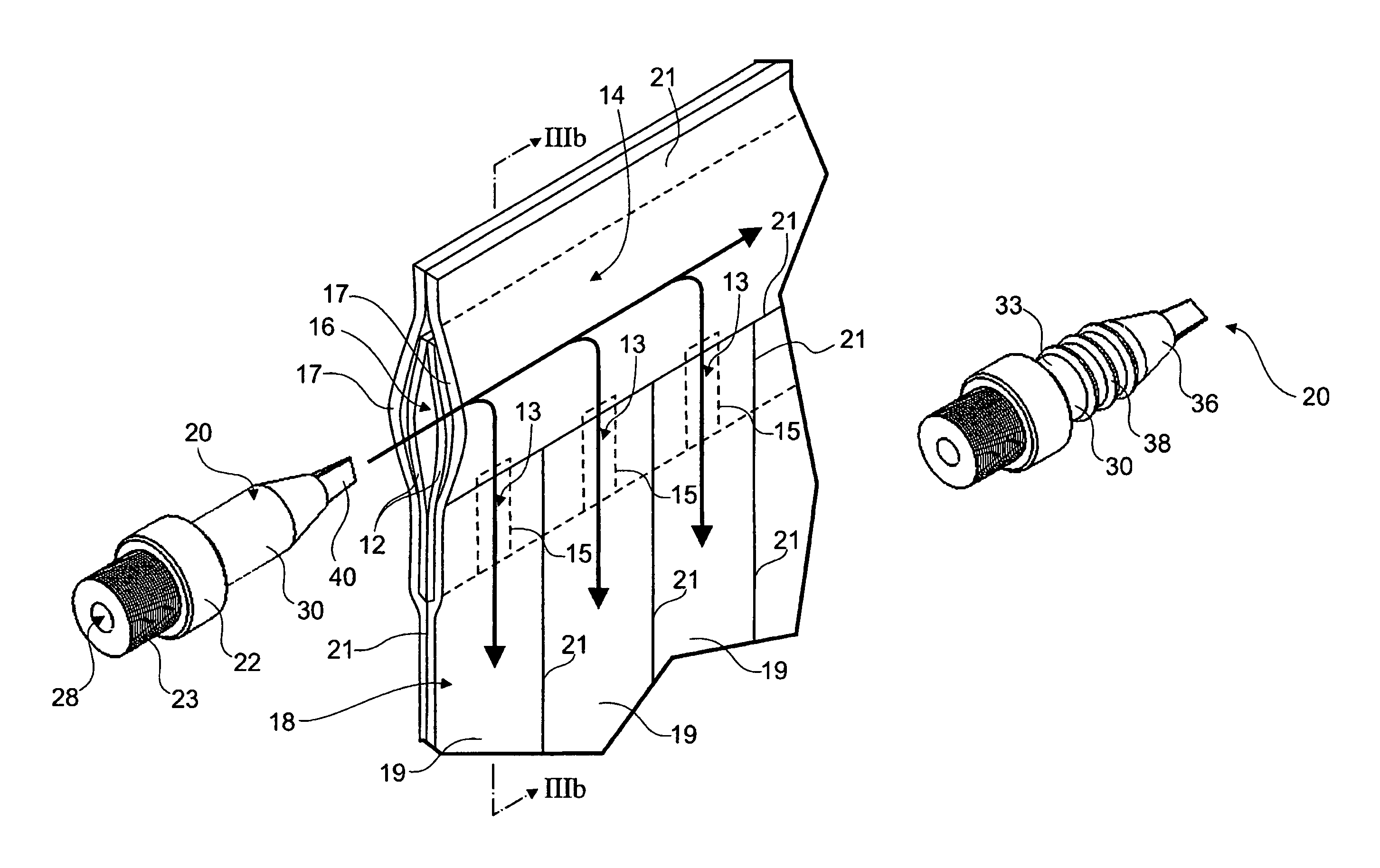
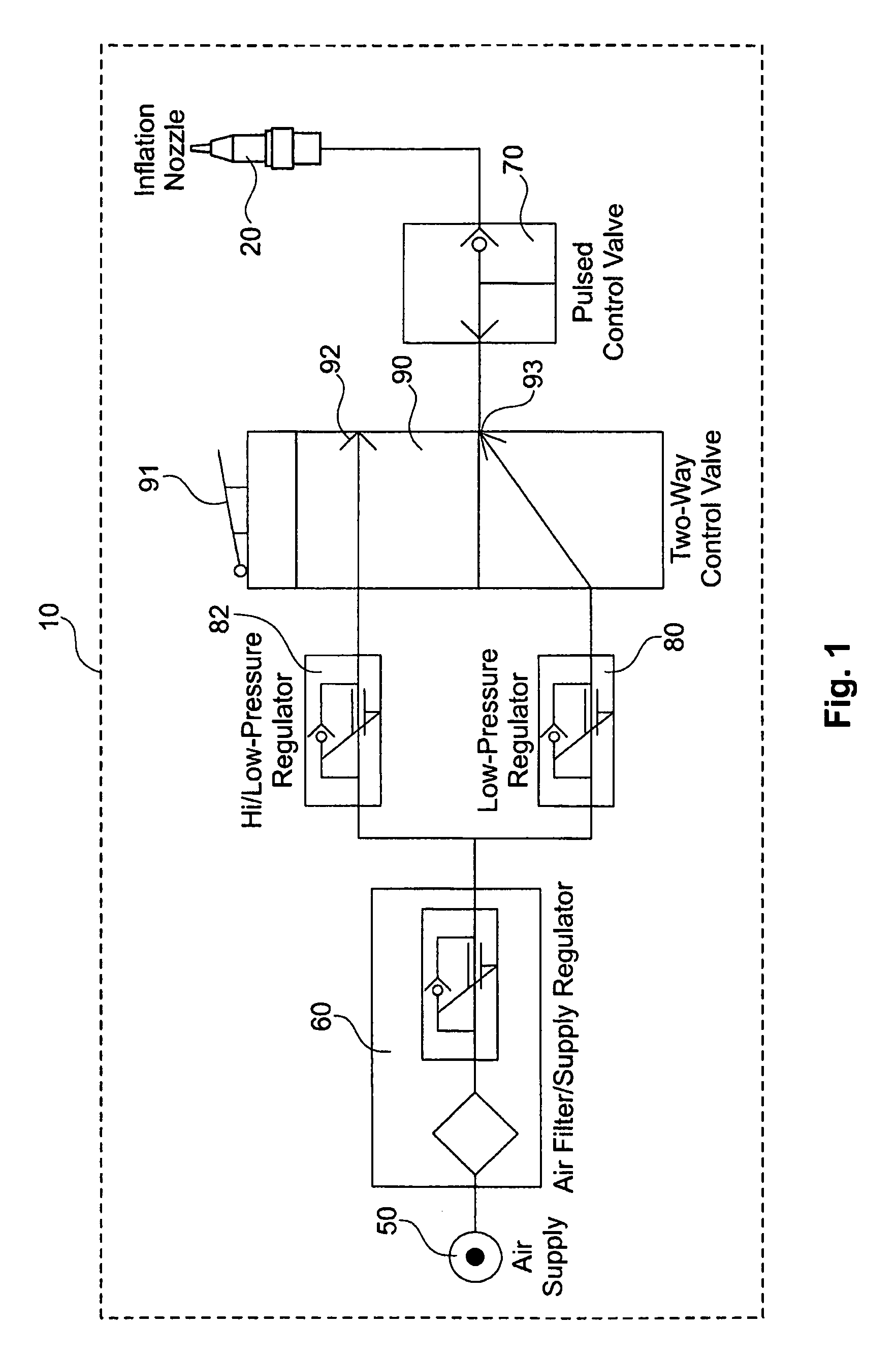
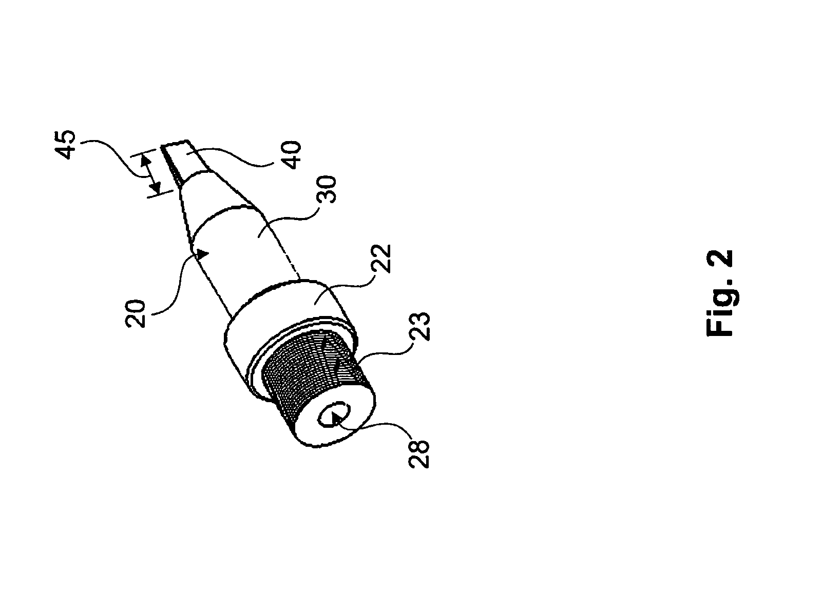
[0025]Referring to FIG. 1, a preferred embodiment of an inflation device 10 includes inflation nozzle 20 that is preferably configured for associating with an inflatable, flexible structure, such as an inflatable air cushion. While the inflation device 10 can be used to inflate a variety of inflatable, flexible structures, such as tires or inflatable mattresses, the remaining sections herein are directed to the applicability of the inflation device 10 with respect to inflatable air cushions and inflatable structures formed of a plurality of flexible sheets that are collapsed onto each other.

[0026]In a preferred embodiment, the inflation nozzle 20 is configured for insertion within an inflation aperture of the air cushion so that a fluid, preferably air, can be delivered through the inflation nozzle 20 into the cushion. The inflation device 10 also includes a fluid source, such as a pressurized air supply 50, that is preferably kept under pressure by a compressor, and a regulator 60 ...


PUM


Abstract

An inflation nozzle for inflating an inflatable structure. The inflation nozzle includes a nozzle body, a probe, and a connection portion. The nozzle body defines a nozzle channel therethrough, and the channel has a channel outlet for expelling a fluid therefrom. The probe extends from the nozzle body adjacent and beyond the channel outlet, and is configured and dimensioned to facilitate positioning an inflation aperture of the flexible structure onto the nozzle body for directing fluid into the inflation aperture. The connection portion associates with the nozzle body for fluidly connecting the channel to a fluid source for delivering fluid through the channel to inflate the flexible structure.

Description

FIELD OF THE INVENTION[0001]The present invention relates to an inflation device, and more particularly to a device for improving the inflation of flexible structures.BACKGROUND OF THE PRESENT INVENTION[0002]Devices are known for use in inflating flexible structures, such as an inflatable air cushion or bag that is used to provide added protection to an object during packaging. One type of air cushion is typically made by sealing plastic sheets to form a series of flexible, plastic, tubular portions that can be connected and adjoined in parallel to or in series with each other. A filler conduit can direct air to the tubular portions via one-way check-valves to inflate the tubular portions and maintain them in an inflated state. Once inflated, the air cushion is typically configured to surround the object that is to be protected, such as by forming a pocket in which the object is placed and then folding over a portion of the inflated air cushion to secure the object therein. An examp...

Claims


Application Information

Patent Timeline
Patent Type & Authority Patents(United States)
IPC IPC(8): F16K15/20
CPCB31D5/0073B31D2205/0088Y10T137/0396Y10T137/3584
Inventor WETSCH, THOMASMCNELLIS, THOMAS
Owner PREGIS INNOVATIVE PACKAGING
Why Eureka
Try Eureka