Side airbag apparatus

a technology of side airbags and stabilizers, which is applied in the direction of pedestrian/occupant safety arrangements, vehicle components, vehicle seats, etc., can solve the problems of variable inflation and deployment directions, inability to protect the occupants in sufficient proportions, and inability to deploy stabilizers in the direction of airbags, etc., to achieve the effect of maintaining the comfort of the vehicle sea

Inactive Publication Date: 2011-04-26
TOYODA GOSEI CO LTD
View PDF3 Cites 87 Cited by
  • Summary
  • Abstract
  • Description
  • Claims
  • Application Information

AI Technical Summary

Benefits of technology

[0008]Accordingly, it is an objective of the present invention to provide a side airbag apparatus that accurately inflates and deploys an airbag toward the front of the vehicle, while maintaining the comfortableness of the vehicle seat.

Problems solved by technology

In this type of side airbag apparatus, sufficient protection of the occupant cannot be achieved simply by inflating and deploying the airbag.
Thus, when the airbag is inflated and deployed, the deployment stabilizing plate interferes with the airbag.
This results in variations in the direction of inflation and deployment.

Method used


Image

  • Side airbag apparatus
  • Side airbag apparatus
  • Side airbag apparatus

Examples


first embodiment

[0025]Hereinafter, a side airbag apparatus according to a first embodiment of the present invention will be described with reference to FIGS. 1 to 5. In the description below, the advancing direction of a vehicle is defined as a forward direction of the vehicle, and a front-rear direction is defined in relation to the forward direction. Also, unless otherwise specified, a vertical direction and a left-right direction coincide with the vertical direction and the left-right direction with respect to the vehicle advancing direction.

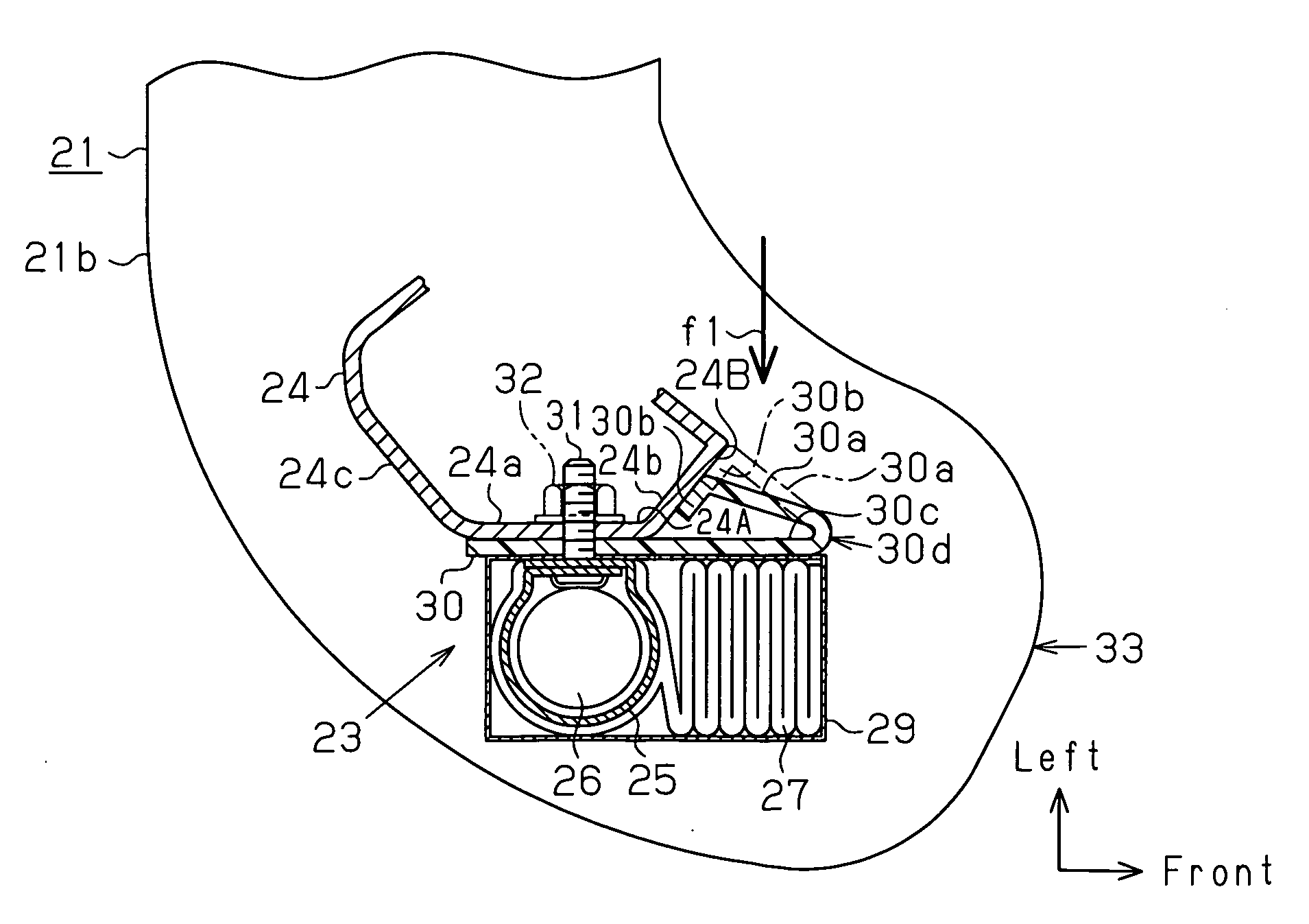
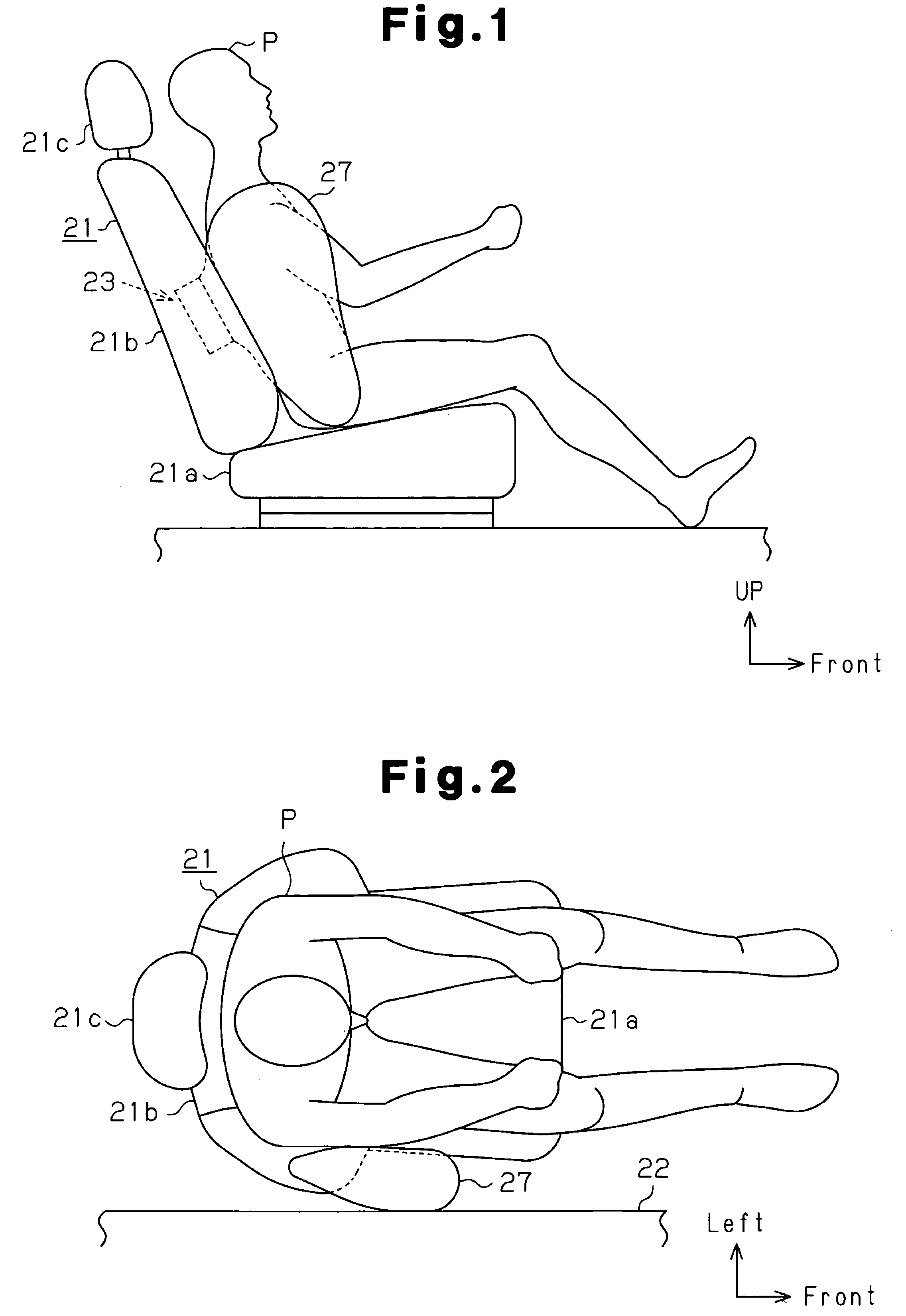
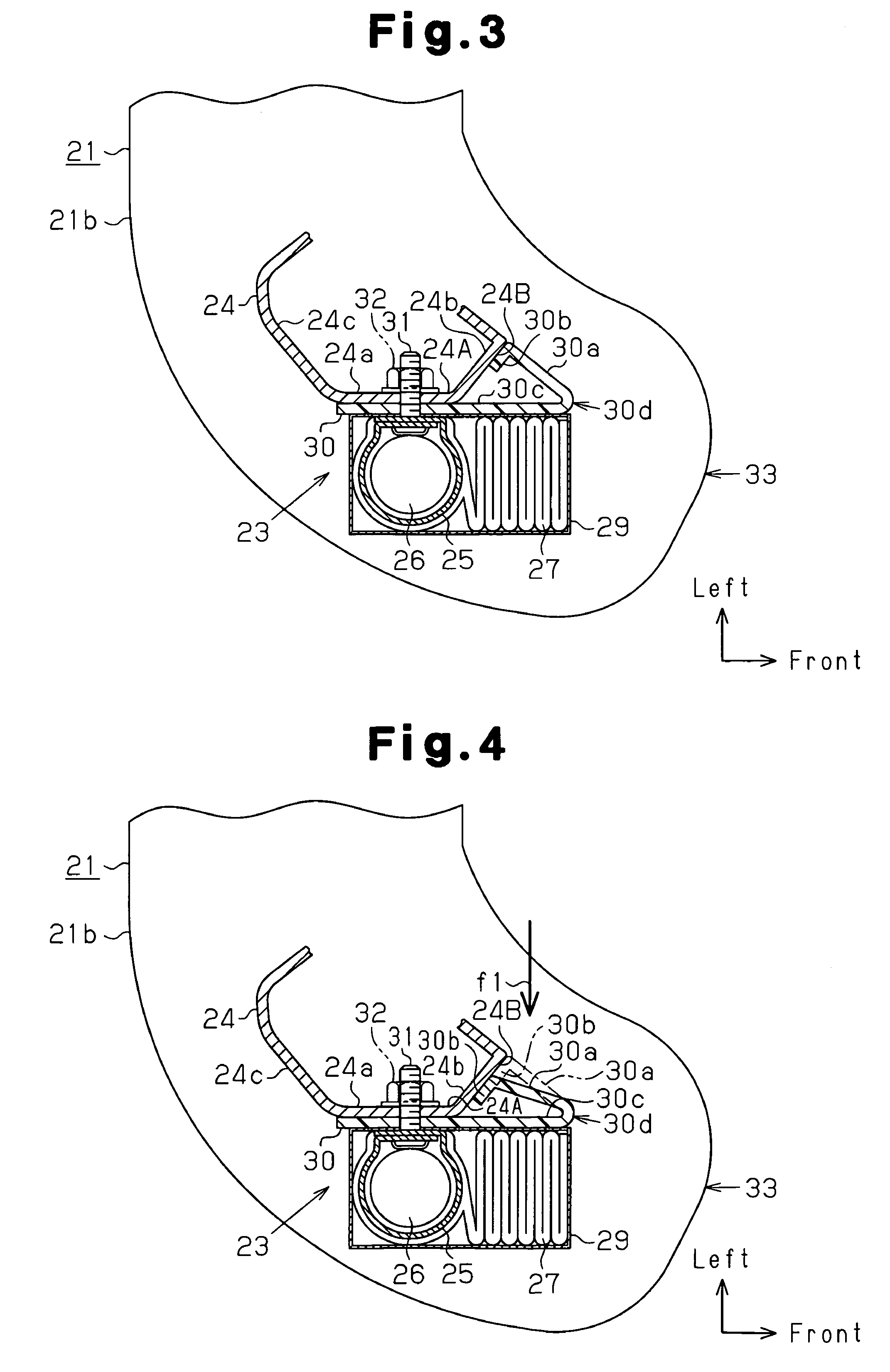
[0026]FIGS. 1 and 2 show a vehicle seat, which is a right front seat 21 (driver's seat), arranged in a passenger compartment of a vehicle. The front seat 21 is a bonded seat, which includes a seat frame 24 (FIGS. 3 to 5), a urethane pad (not shown) put over the seat frame 24, and a cover (not shown) adhered to the urethane pad. The front seat 21 is arranged on the floor of the passenger compartment and includes a seat cushion 21a, a seatback 21b, and a headr...

second embodiment

[0045]A second embodiment of the present invention will now be described. The differences from the first embodiment will mainly be discussed.

[0046]In place of the guide member 30 of the first embodiment, a side airbag apparatus 23 of the second embodiment has a guide member 40 shown in FIG. 6. A spacer (not shown) is located between the guide member 40 and the retaining cover 29 to create a gap. That is, the guide member 40 has a plate-like guide portion 40c, a hinge 40d, a flexible portion 40a, and a rib 40b. The guide portion 40c is fixed to the seat frame 24 with a bolt 31 extending in the front-rear direction. The hinge 40d is formed by a part of the guide portion 40c that is fixed with the bolt 31. The hinge 40d is located in a center of the guide portion 40c with respect to the front-rear direction. The flexible portion 40a is formed by a part of the guide portion 40c that is forward of the hinge 40d. The rib 40b is located on the left side surface of the flexible portion 40a ...

third embodiment

[0054]A third embodiment of the present invention will now be described. The differences from the second embodiment will mainly be discussed.

[0055]A side airbag apparatus 23 according to a third embodiment is different from the second embodiment in that a contact rib 40e on the right side surface of the guide portion 40c of the guide member 40 as shown in FIG. 9. The contact rib 40e has a right triangular cross section. The rear end of the contact rib 40e is adjacent to the bolt 31, and the distal end (right end) of the contact rib 40e contacts the retainer 25 with the retaining cover 29 and the airbag 27 in between. A hinge 40d is provided in a part of the guide portion 40c that is adjacent to the front end of the contact rib 40e. A flexible portion 40a is provided in a part of the guide portion 40c that is forward of the hinge 40d. The hinge 40d is located at a position that corresponds to the front end 24A of the right side wall 24a.

[0056]When the occupant P sits in the front se...


PUM


Abstract

A side airbag apparatus 23 includes an airbag 27 and a guide member 30, which guides inflation and deployment of the airbag 27. The airbag 27 is fixed to a right side wall 24a of a seat frame 24. A part of the airbag 27 protrudes further forward than a front end 24A of the right side wall 24a. The airbag 27 is supplied with gas from an inflator 26, so as to be inflated and deployed in a space between a body side portion of a vehicle and an occupant seated in a front seat 21. The guide member 30 guides the airbag 27 forward when it is inflated and deployed. The guide member 30 includes a guide portion 30c and a first bending portion 30a, which extends from the guide portion 30c. The guide portion 30c is arranged to face a surface of the airbag 27 facing the interior of the vehicle at least in an area forward of the right side wall 24a. The first bending portion 30a is flexed rightward when receiving load from the left. Also, the first bending portion 30a restricts the guide portion 30c from being flexed leftward when receiving the force of inflation and deployment of the airbag 27.

Description

BACKGROUND OF THE INVENTION[0001]The present invention relates to a side airbag apparatus having an airbag that is inflated and deployed in a space on a side of an occupant.[0002]Typically, a side airbag apparatus inflates and deploys an airbag in a space on a side of an occupant when an impact of a magnitude greater than or equal to a predetermined value is applied to the body side portion of a vehicle. By reducing the impact applied to the occupant with the inflated airbag, the apparatus protects the head, the thorax, or the lumbar region. In such a side airbag apparatus, gas is injected to the interior of the airbag by a gas generator so that the airbag is instantly inflated and deployed (for example, Japanese Laid-Open Patent Publication No. 2006-137398).[0003]In this type of side airbag apparatus, sufficient protection of the occupant cannot be achieved simply by inflating and deploying the airbag. That is, the airbag needs to be inflated and deployed into an intended state at ...

Claims


Application Information

Patent Timeline
Patent Type & Authority Patents(United States)
IPC IPC(8): B60R21/207B60R21/20B60N2/42
CPCB60R21/207
Inventor OKADA, IZURUKANTO, TAKANORI
Owner TOYODA GOSEI CO LTD
Why Eureka
Try Eureka