Orthopedic splints

a technology of orthopaedic splints and splints, which is applied in the field of orthopaedic splints, can solve the problems of inability to reform the thermosetting plastic or fiberglass-reinforced resin splint once cured, the preformed metal splints are also quite rigid and difficult to bend or mold, and patients are at increased risk of injury, etc., to achieve convenient portability and storage, and ensure the effect of precis

Inactive Publication Date: 2006-01-31
THE SEABERG
View PDF30 Cites 13 Cited by
  • Summary
  • Abstract
  • Description
  • Claims
  • Application Information

AI Technical Summary

Benefits of technology

[0009]The present invention provides an answer to some of the shortcomings of the previously available splints, by providing a splint that can readily and precisely conform to the elbow and ankle, that is

Problems solved by technology

These splints are designed to rigidly prevent motion and once formed into position cannot be reformed, for example to accommodate swelling, without considerable difficulty.
A thermosetting plastic or fiberglass-reinforced resin splint once cured cannot be reformed.
Preformed metal splints are also quite rigid and difficult to bend or mold.
None of the above mentioned splints once formed allow a patient to perform any significant active movement or provide variably controlled acti

Method used


Image

  • Orthopedic splints
  • Orthopedic splints
  • Orthopedic splints

Examples


Embodiment Construction

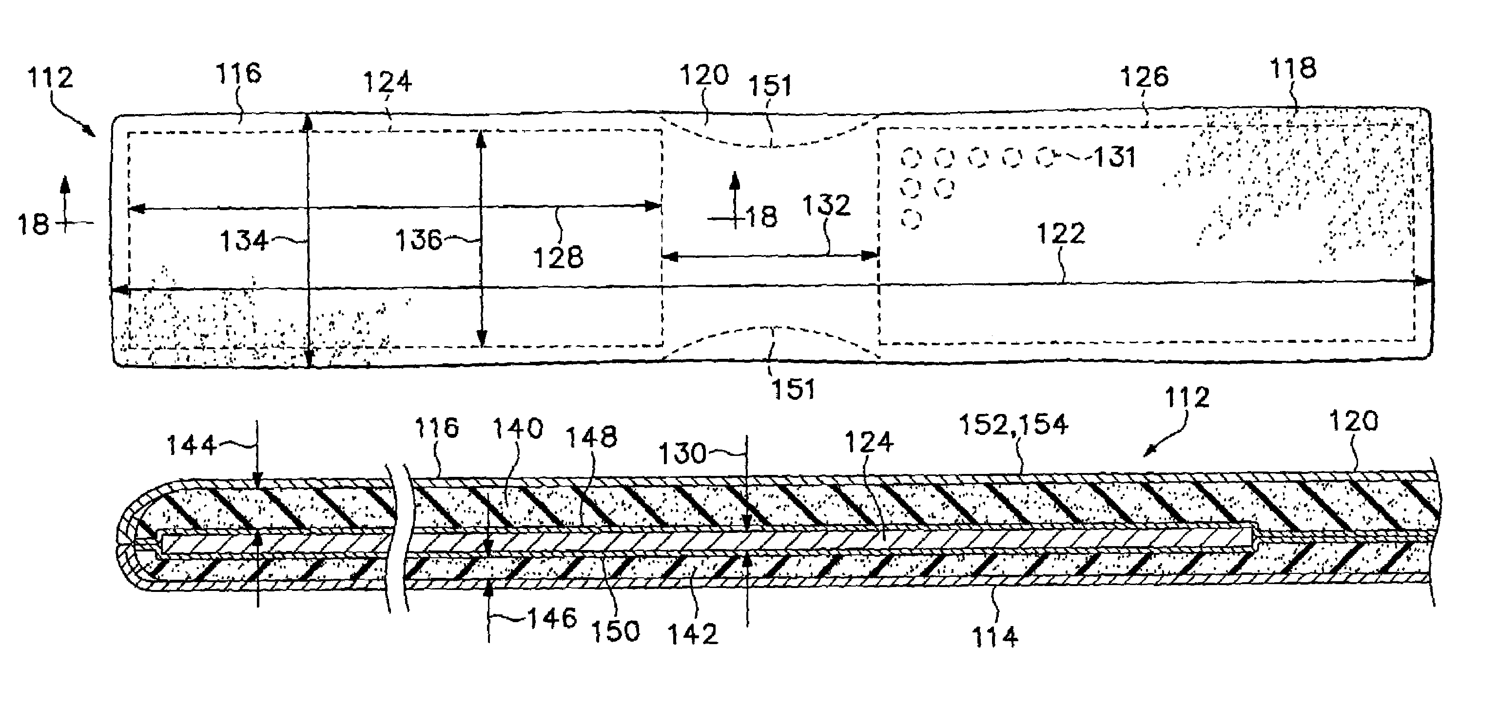
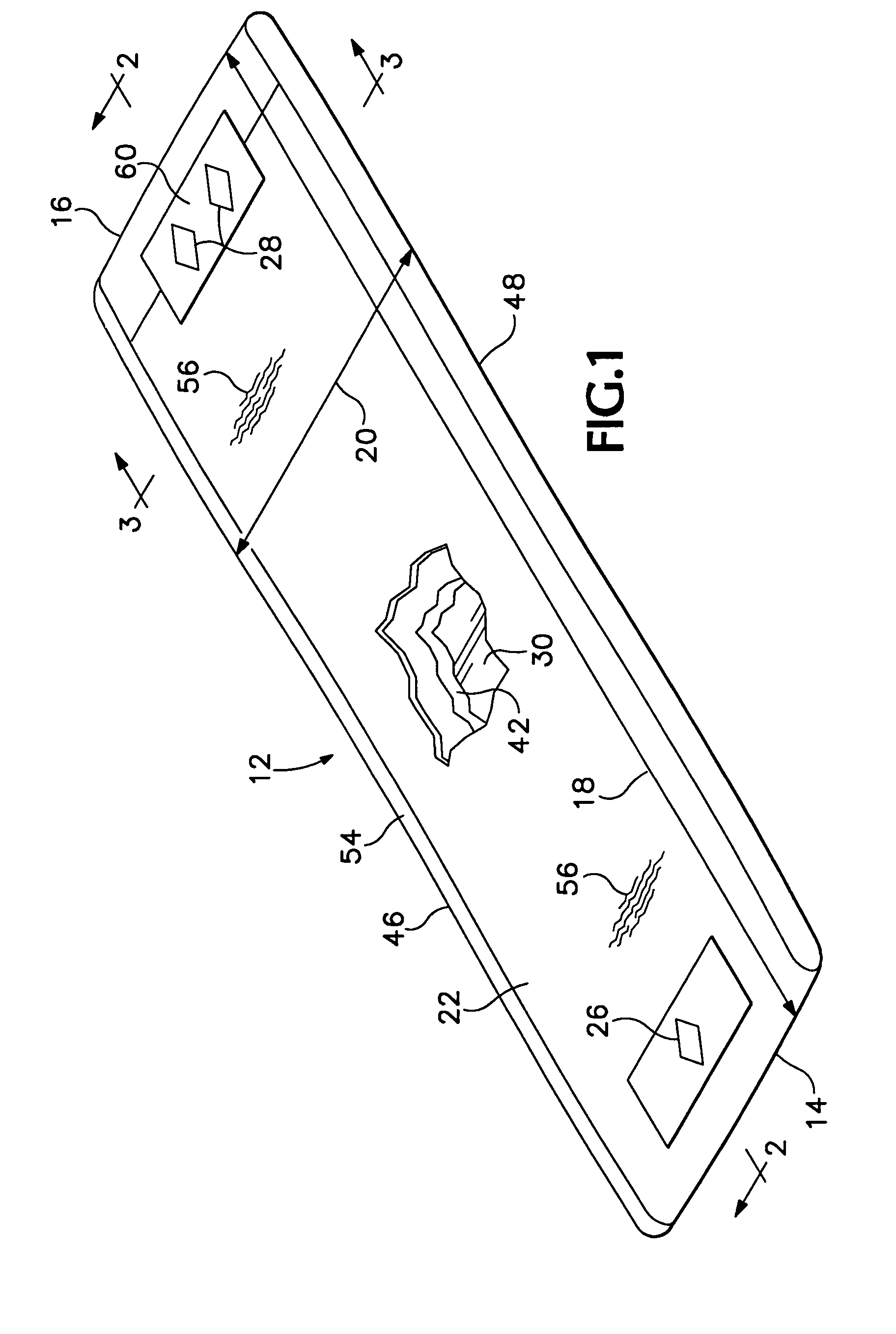
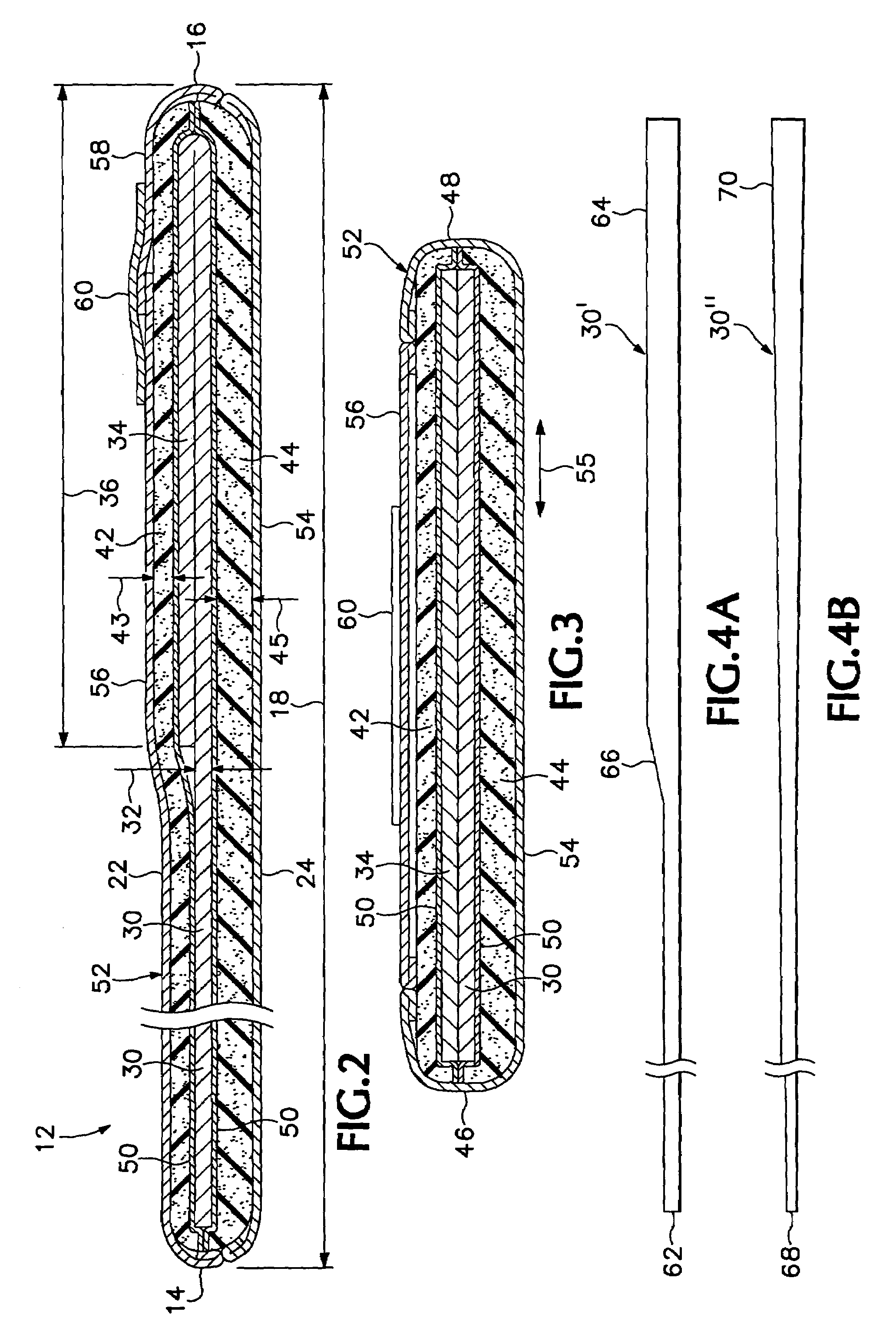
[0046]Referring now to the drawings which form a part of the disclosure herein, in FIGS. 1 and 2 a splint 12 which is a first preferred embodiment of the present invention is shown in a generally planar configuration in which the splint is manufactured and is usually packaged for shipment and for storage prior to its use. A body of the splint 12 has a first end 14 and an opposite second end 16 defining a length 18 that is greater than the width 20. For example, the length 18 may be twelve to fifteen inches and the width 20 may be in the range of four to six inches, and preferably about 4½ inches for a splint 12 intended for use to support the wrist of an adult.

[0047]The body of the splint has a skin contact, or closer face 24, intended to be placed in contact with a patient's skin or wound dressing, and shown in FIG. 2, but facing downward in FIG. 1. An opposite or farther face 22 of the splint facing upward, in FIG. 1, and normally faces outward, away from a patient's skin when the...


PUM


Abstract

An orthopedic wrist splint with an initially generally planar malleable metal core covered by a layer of synthetic foam padding material on each of its opposite sides and protected by an outer cover of fabric. In one embodiment, depending on the orientation of the splint relative to the patient, the splint provides greater or lesser firmness of support when the core is bent to conform the splint to the patient's hand, wrist, and forearm. In another embodiment, a central part of the length of the splint lacks the metal core and is flexible, so that two parts of the splint are easily used on opposite sides of an arm or ankle, with the central part comfortably bent around an elbow or a foot, and with the splint firmly supporting the limb.

Description

CROSS-REFERENCE TO RELATED APPLICATIONS[0001]This application is a continuation-in-part of co-pending application Ser. No. 10 / 357,659, filed Feb. 3, 2003.BACKGROUND OF THE INVENTION[0002]The present invention relates to splints for immobilizing injured body members, and particularly to an improved splint that can be shaped to support a patient's hand, wrist, and forearm in comfort, and a method for its use.[0003]Splints for use in emergency and post-operative situations are known, for example, from Scheinberg, U.S. Pat. Nos. 4,676,233 and 3,943,923, both of which teach the use of a soft metal sheet formed into a configuration that provides needed support for an injured limb. Bentele U.S. Pat. No. 4,161,175 discloses surgical splints incorporating formed sheet metal or molded plastic bases. Ender U.S. Pat. No. 4,549,537 discloses another splint based on the use of sheet aluminum material. Bolla et al. U.S. Pat. No. 6,039,706 discloses a splint using a sheet of corrugated metal as its...

Claims


Application Information

Patent Timeline
IPC IPC(8): A61F5/00A61F5/01
CPCA61F5/0111A61F5/05866A61F5/05825A61F5/0118
Inventor SCHEINBERG, SAMUELPOLLIACK, ADRIAN A.
Owner THE SEABERG
Why Eureka
Try Eureka