Method and apparatus for measuring viscosity

Inactive Publication Date: 2007-10-23
EHWALD RUDOLF +4
View PDF9 Cites 3 Cited by
  • Summary
  • Abstract
  • Description
  • Claims
  • Application Information

AI Technical Summary

Benefits of technology

[0020]By positioning the measuring zone in a measuring chamber and by connecting it through pores with the medium for the convective or diffusive exchange of material, the influence of movements in the fluid to be analyzed upon the measuring process is reduced or eliminated. Where the measuring chamber is completely enclosed by a dialysis membrane, a diffusion equilibrium relative to the exterior solution will be established within a short period. This may be realized, for instance, by a silicon body provided with a rod-like thin point containing the cantilevered conductor arrangement and positioned within the lumen of a hollow fiber without completely filling the lumen such that the space between the membrane of the hollow fiber and the silicon body is structured as a chamber wherein the measuring zone is contained.
[0022]Where the substrate used is a silicon body, it is possible by modern fabrication technologies to integrate circuits for collecting, converting and outputting signals, thereby facilitating the manufacture of a conveniently portable semi-invasive sensor. Given the current state of high frequency technology, the invention also makes possible the development of a completely implantable sensor providing for wireless signal transmission.
[0023]In accordance with the method of the invention of measuring viscosity, at least one passivated resiliently movable thin conductor supported in a cantilevered manner within the measuring zone is repulsed and attracted and moved by a sequentially changing magnetic field or by an electrical high frequency signal of sequentially changing amplitude. Where the power is generated by an electrical high frequency field, the use of very high frequencies is advantageous as it substantially neutralizes the effect of the power on the solution in the measuring zone. The rate of the electrically or electromagnetically induced change of position, or of the resilient relaxation of the cantilevered movable conductor into its initial position, is a function of the viscosity of the fluid and may be detected, for instance, by measuring the capacitance or impedance between the moveable conductor and a conductor in the substrate disposed a small distance from the moveable conductor.
[0024]Passivated aluminum wire has been found to be a particularly advantageous material for making movable conductors because it can be easily integrated in the silicon body and because of its favorable ratio of electrical conductivity to weight or mass. The utilization of very high frequencies, for instance in the GHz range, is also advantageous for measuring the distance in view of the fact that it makes it possible to measure the capacitance substantially independently of the electric conductivity of the analyzed fluid.
[0028]The advantages of the apparatus thus defined, the structure, fabrication and use of which will be described hereinafter in connection with a preferred embodiment, are that it lends itself to miniaturization, to fabrication processes well-known in silicon technology and that it makes possible practicable methods of detecting viscosity-dependent parameters in a small volume and at short intervals.

Problems solved by technology

However, measurements with conventionally used viscometers, such as, e.g. rotation viscometers or capillary viscometers, usually require relatively large quantities of fluid.
It is, however, unlikely that such a system may be realized in an implanted sensor.
Such and similar sensors based upon the attenuation of oscillations (e.g. German Patent specification 198 06 905) cannot, however, be applied to measuring the viscosity of small quantities of highly viscous fluids in which no oscillations can be generated because of the extremely high attenuation.
Other known or obvious possibilities of measuring the viscosity in very small fluid volumes, such as, for instance, an optical analysis of Brownian particle movement, electrophoresis or dielectrophoresis, may not easily be applied to highly viscous polymeric solutions of an undefined electrolyte composition.
Hitherto, no apparatus adaptable to miniaturization and cost efficient fabrication has become known which is suitable for taking precise measurements of high viscosities in a very small and static measuring zone, such as, for example, a dialysis chamber, and for converting such measurements into electrical signals.

Method used


Image

  • Method and apparatus for measuring viscosity
  • Method and apparatus for measuring viscosity
  • Method and apparatus for measuring viscosity

Examples


Embodiment Construction

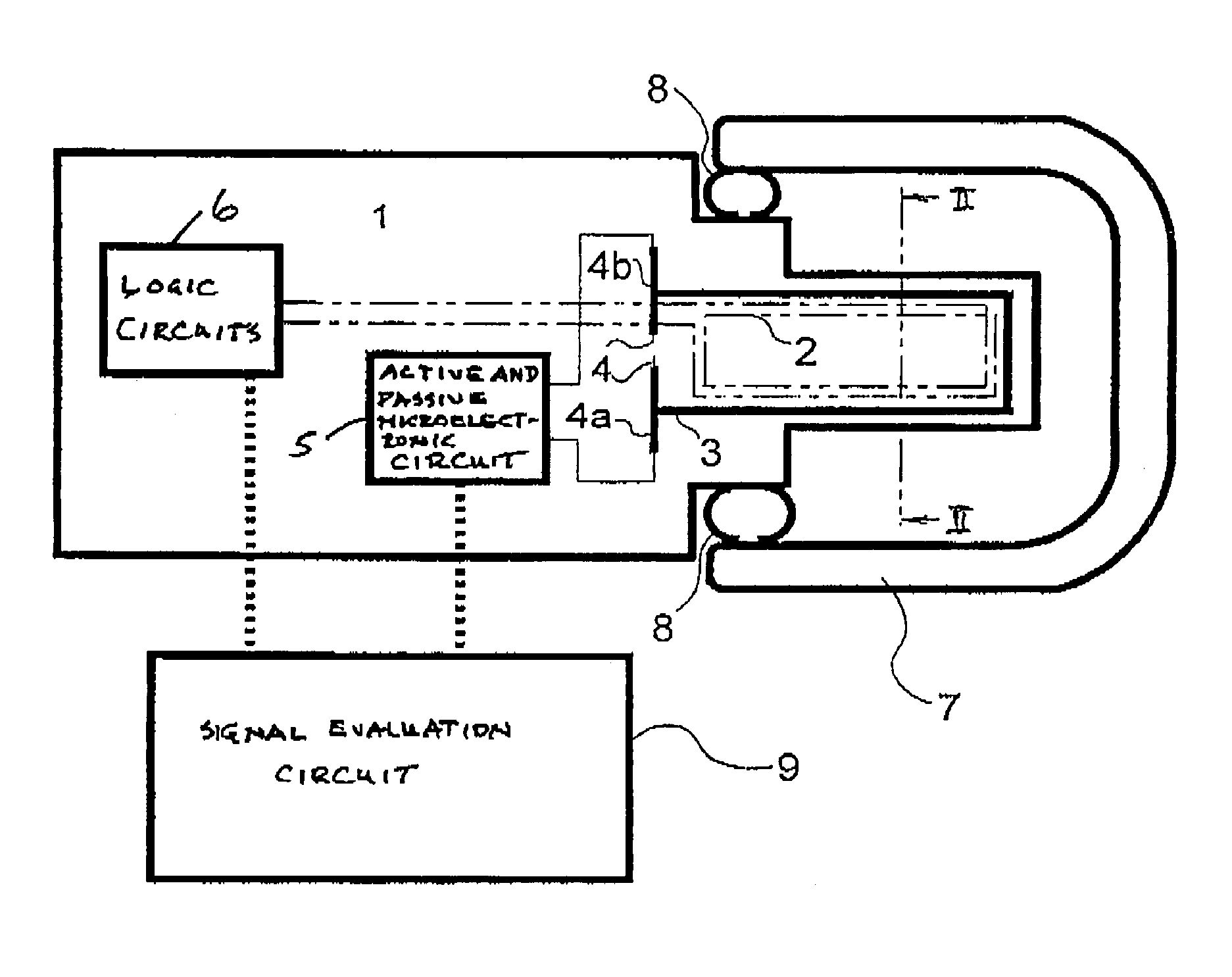
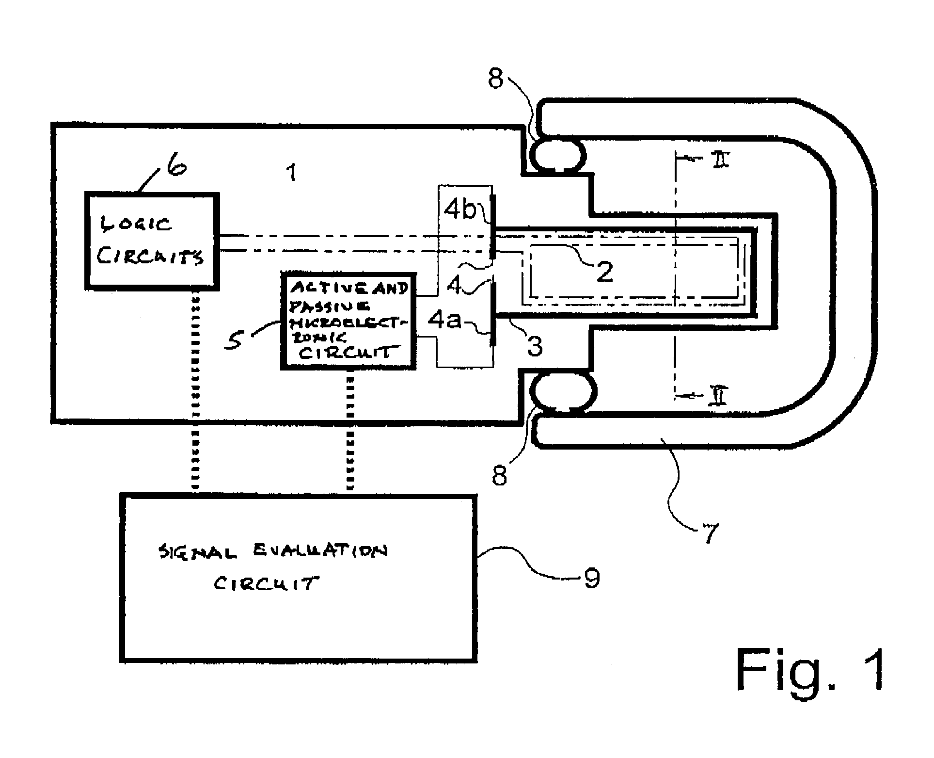
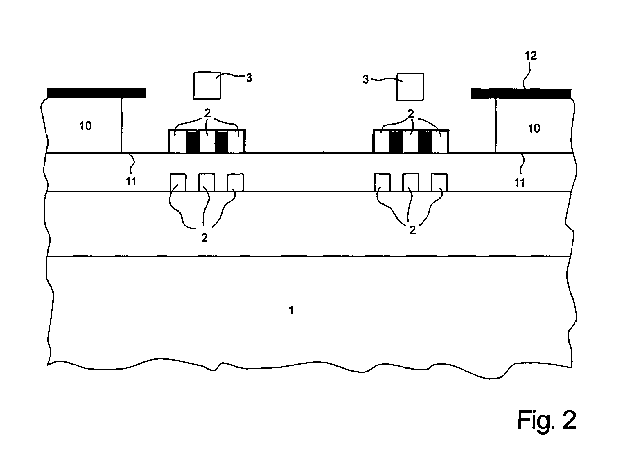
[0032]A preferred embodiment of the invention will hereinafter be described with reference to FIG. 1 and FIG. 2. An elongate body or substrate 1 of silicon of substantially square cross section is provided at its right end, as seen in FIG. 1, with a substantially coaxially disposed extension, hereinafter sometimes referred to as a tip, of reduced diameter. By way of example, the length and width of the extension may be about 1 mm and about 300 μm, respectively. The extension supports energy conducting loops made of aluminum, disposed in parallel and connected to sources of energy (not shown). The energy may be direct current and / or high frequency voltage, preferably in the Ghz range. Some of the energy conducting loops, hereinafter referred to as loops, are connected in series and form a flat or loop coil 2 rigidly connected to, or embedded in, the silicon substrate. A further loop 3 made from passivated aluminum and disposed in a measuring zone is extending in a cantilevered fashio...


PUM


Abstract

An apparatus for measuring the viscosity of a fluid having a first rigid member extending from a body of semiconductor material and provided with a first conductive path and a second resiliently flexible member provided with a second conductive path and arranged in cantilever fashion over the rigid member. At least one of the conductive paths may be selectively energized to brig about relative movement between the rigid and flexible member. Subsequent deenergization of the path causes the resiliently flexible member to return to its initial position, the rate of return being measured to derive a signal representative of the viscosity. Also described are methods of carrying out the measurement and of fabricating the apparatus.

Description

BACKGROUND OF THE INVENTION[0001]1. Field of the Invention[0002]The invention, in general, relates to a method of, and to an apparatus for, measuring viscosity and, more particularly, to the viscometric measurement of minute quantities of fluid substances.[0003]2. The Prior Art[0004]The viscometric observation of the activity of hydrolytic enzymes, the speed of polymeric synthesis, the course of clotting or coagulation processes and of other biotechnologically important processes is well-known. However, measurements with conventionally used viscometers, such as, e.g. rotation viscometers or capillary viscometers, usually require relatively large quantities of fluid. As described by W. M. Kulicke in Flowing Behavior of Substances and Substance Mixtures (Hüthig Wepf. publ. Basel, Heidelberg, New York, 1986), samples of the fluids are removed from their environment and transferred to the measuring device.[0005]Yet for many tasks in polymer chemistry, biochemistry and physiology there e...

Claims


Application Information

Patent Timeline
IPC IPC(8): G01N11/10A61B5/00G01N11/16
CPCA61B5/14532G01N11/16G01N13/02G01N2203/0094G01N2011/008
Inventor EHWALD, RUDOLFEHWALD, KARL-ERNSTKNOLL, DIETERWINKLER, WOLFGANGZINKE, HENNING
Owner EHWALD RUDOLF
Why Eureka
Try Eureka