Buckle pretensioner system

a pretensioner and buckle technology, applied in the direction of pedestrian/occupant safety arrangement, vehicular safety arrangement, safety belt, etc., can solve the problems of large load being applied to the vehicle occupant, and the comfort of the vehicle occupant is reduced, so as to reduce the occurrence of occurrence, preserve comfort, and simple configuration

Active Publication Date: 2009-04-14
KK TOKAI RIKA DENKI SEISAKUSHO
View PDF30 Cites 14 Cited by
  • Summary
  • Abstract
  • Description
  • Claims
  • Application Information

AI Technical Summary

Benefits of technology

[0010]In view of this problem, there is needed a buckle pretensioner system that can preserve comfort when a vehicle occupant is seated and can suppress the occurrence of the “submarine phenomenon” when the vehicle experiences a sudden deceleration (i.e., when, in the event of a collision, the body of a vehicle occupant catches on the seat belt and slides underneath even though the seat belt is being worn by the vehicle occupant).

Problems solved by technology

If the vehicle suddenly decelerates and the pretensioner system is actuated in this state, a large load ends up being applied to the vehicle occupant from the webbing belt.
However, in systems where such countermeasures have been administered, there has been the drawback that the comfort is reduced when the vehicle occupant is seated in the seat.

Method used


Image

  • Buckle pretensioner system
  • Buckle pretensioner system
  • Buckle pretensioner system

Examples


first embodiment

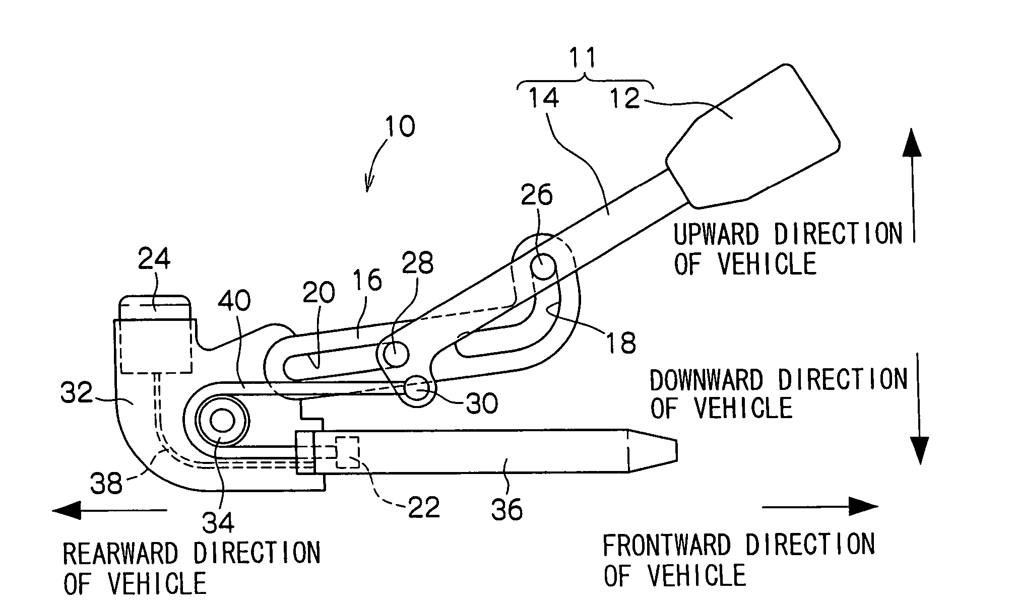
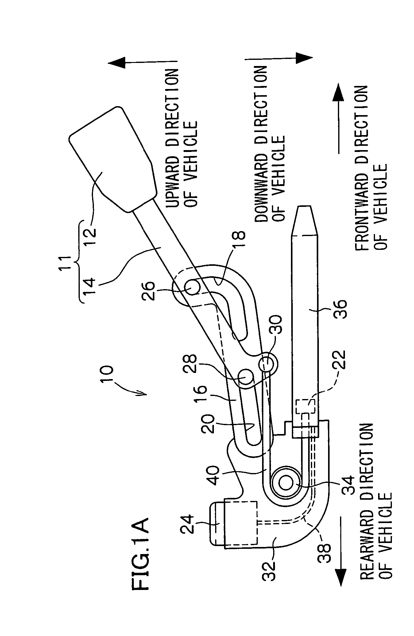
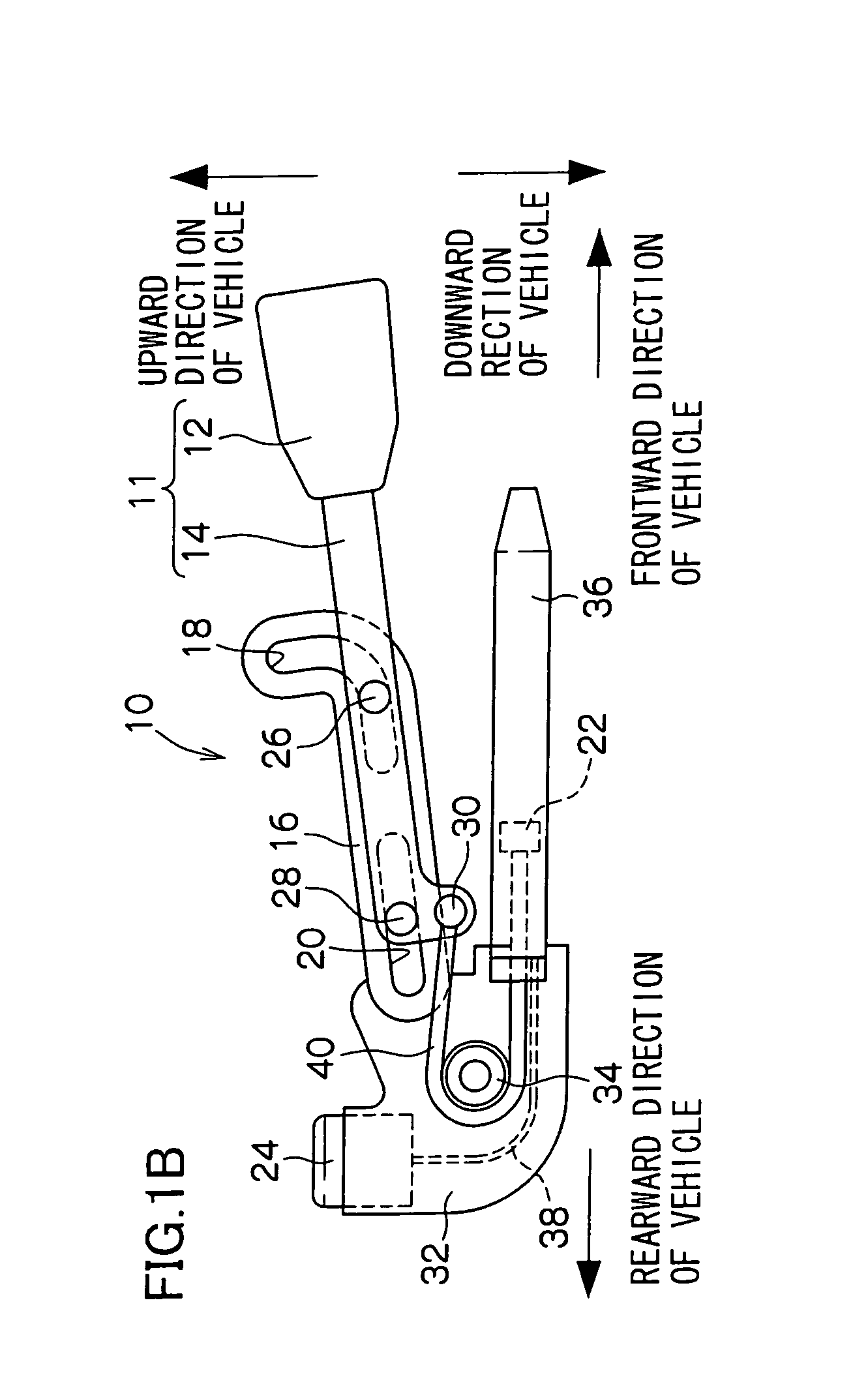
[0088]A buckle pretensioner system 10 pertaining to a first embodiment of the invention is shown in side view in FIGS. 1A to 1C.

[0089]The buckle pretensioner system 10 is disposed with a base plate 32. The base plate 32 is fixed, by an attachment bolt and via a seat rail of a vehicle body, to the side surface (portions without reference numerals are not shown in the drawings) of a seat frame that is supported so that its position can be adjusted in the front-rear direction of the vehicle.

[0090]A roller 34 is disposed in the vehicle vertical direction center and the vehicle front-rear direction center of the base plate 32. The roller 34 is axially supported by the base plate 32 so as to be rotatable using the vehicle left-right direction as the axial direction.

[0091]A cylinder 36 is coupled to the front side of a lower end portion of the base plate 32. A piston 22 is housed in the cylinder 36 so as to be movable in the front-rear direction of the vehicle.

[0092]A gas generator 24 is d...

second embodiment

[0117]A buckle pretensioner system 50 pertaining to a second embodiment of the invention is shown in side view in FIGS. 2A to 2C.

[0118]The buckle pretensioner system 50 is disposed with a cylinder 52. The cylinder 52 is fixed to a vehicle (not shown) inside the vehicle cabin using the front-rear direction of the vehicle as the axial direction.

[0119]A guide-use piston 54 is housed inside the cylinder 52 so as to be movable in the front-rear direction of the vehicle. The guide-use piston 54 includes a bar-like rod 55 that extends from the guide-use piston 54 in the frontward direction of the vehicle and whose tip end portion is rounded. When the guide-use piston 54 moves in the frontward direction of the vehicle, the rod 55 protrudes via a protrusion hole 52A formed in the front side of the cylinder 52. When the rod 55 protrudes to the outside of the piston 52 in correspondence to a later-described buckle 67, the rod 55 pushes against a buckle stay 70 of the buckle 67 so that a buckle...

third embodiment

[0147]A buckle pretensioner system 80 pertaining to a third embodiment of the invention is shown in side view in FIGS. 3A to 3C.

[0148]The buckle pretensioner system 80 is disposed with a cylinder 82. The cylinder 82 is attached to a vehicle (not shown) inside the vehicle cabin in a state where the axial direction is somewhat slanted in the upward direction of the vehicle from the vehicle rear towards the vehicle front.

[0149]A piston 84 is housed inside the cylinder 82 so as to be movable in the front-rear direction of the vehicle along the axial direction of the cylinder 82.

[0150]The front side of the cylinder 82 along the axial direction is open. The lower end wall of the lower side of the open place (called “open portion” below) extends further in the frontward direction of the vehicle along the axial direction of the cylinder 82 than the upper end wall of the upper side of the open portion, is formed as a stopper 96 for stopping the pivoting of a later-described buckle 91, and co...


PUM


Abstract

A buckle pretensioner system includes a substantially L-shaped rail for guiding a buckle body of a buckle from a position where the buckle body engages with a tongue plate to a position corresponding to a lumbar region of a vehicle occupant. When a vehicle disposed with the buckle pretensioner system undergoes a sudden deceleration, a piston inside a cylinder is moved in a frontward direction of the vehicle by gas generated by the actuation of a gas generator, a buckle stay is pulled by a wire coupled to the piston, and the buckle stay is moved along the shape of the rail. As a result, the buckle body supported by the buckle stay pivots from the position where the buckle body engages with the tongue plate to a vehicle occupant restraining position of a webbing belt, and then is pulled to the lumbar region-corresponding position.

Description

CROSS-REFERENCE TO RELATED APPLICATION[0001]This application claims priority under 35 USC 119 from Japanese Patent Application No. 2004-169656, the disclosure of which is incorporated by reference herein.BACKGROUND OF THE INVENTION[0002]1. Field of the Invention[0003]The present invention relates to a buckle pretensioner system which, when a vehicle disposed with the buckle pretensioner system undergoes a sudden deceleration, pulls, in a vehicle occupant restraining direction of a webbing belt for restraining a vehicle occupant, a buckle that engages with a tongue plate inserted through an intermediate portion of the webbing belt.[0004]2. Description of the Related Art[0005]In a seat belt device, a tongue plate inserted through an intermediate portion of a webbing belt is inserted into and engages with a buckle, whereby the body of a seated vehicle occupant is restrained by the webbing belt.[0006]There are also seat belt devices disposed with a pretensioner system that improves the ...

Claims


Application Information

Patent Timeline
Patent Type & Authority Patents(United States)
IPC IPC(8): B60R22/28B60R22/195B60R22/46B60R22/36
CPCB60R22/1951B60R22/1952B60R22/1955
Inventor KOIDE, TERUHIKOMUTO, KOJINOJIRI, MASAYOSHIMIYAGAWA, TOSHIHITO
Owner KK TOKAI RIKA DENKI SEISAKUSHO
Why Eureka
Try Eureka