Vehicle seat and vehicle

a technology for vehicles and seats, applied in the direction of movable seats, process and machine control, instruments, etc., can solve the problems of seated vehicle occupants being impeded by nearby interior components, and the feet (i.e., the toes) of the seated vehicle occupants being impeded

Inactive Publication Date: 2017-02-23
TOYOTA JIDOSHA KK
View PDF1 Cites 11 Cited by
  • Summary
  • Abstract
  • Description
  • Claims
  • Application Information

AI Technical Summary

Benefits of technology

[0008]In consideration of the above-described circumstances, the present disclosure provides a vehicle seat that can be rotated inside a vehicle ca

Problems solved by technology

Namely, in the above-described vehicle seat, because the entire feet of the seated vehicle occupant protrude beyond the seat cushion toward the seat front side, when the vehicle seat is rotated, there is a possibility of the feet (i.e., the toes) of the seated vehicle occupant being impeded by nearby interior components (such as other seats or components and the l

Method used


Image

  • Vehicle seat and vehicle
  • Vehicle seat and vehicle
  • Vehicle seat and vehicle

Examples


first embodiment

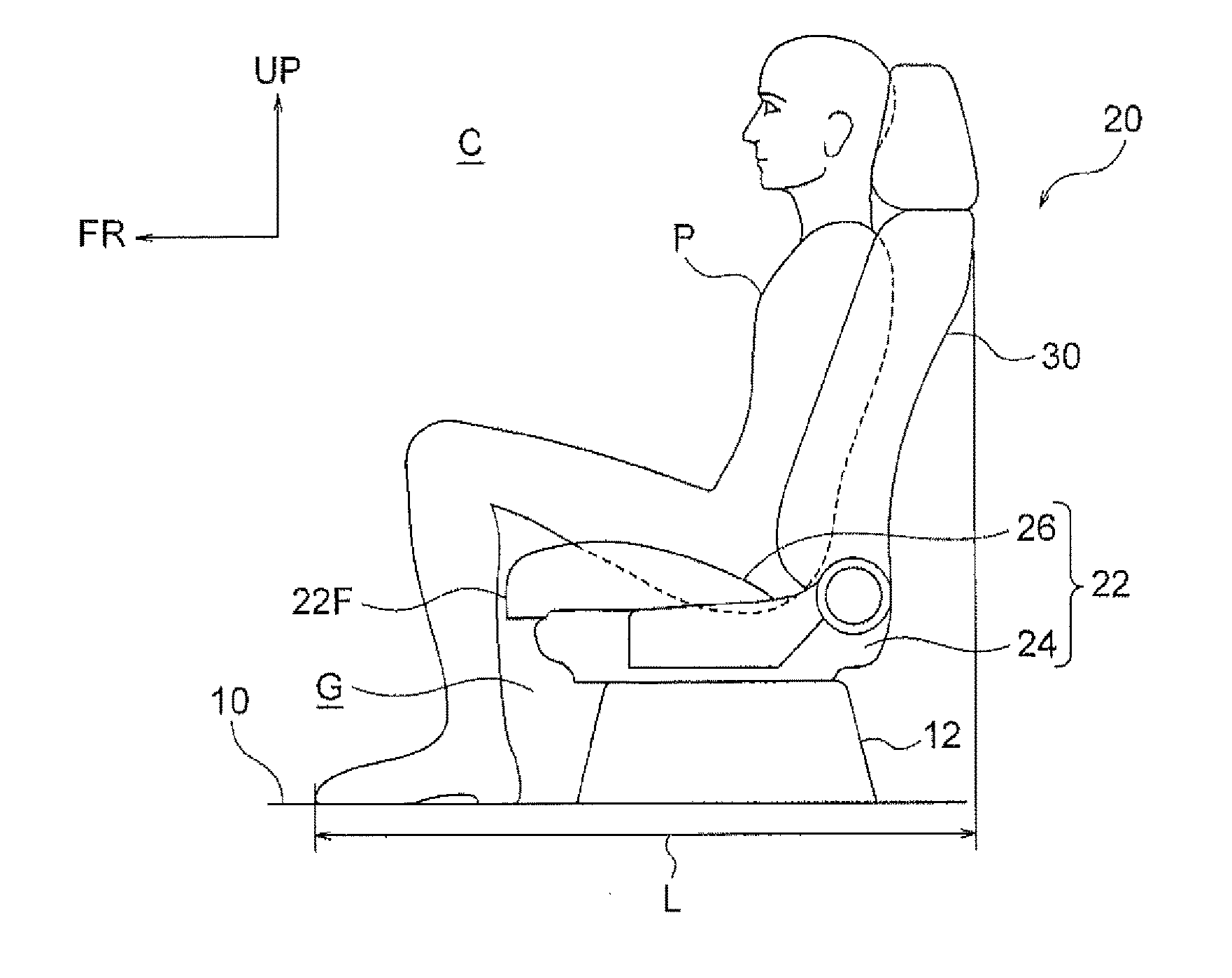
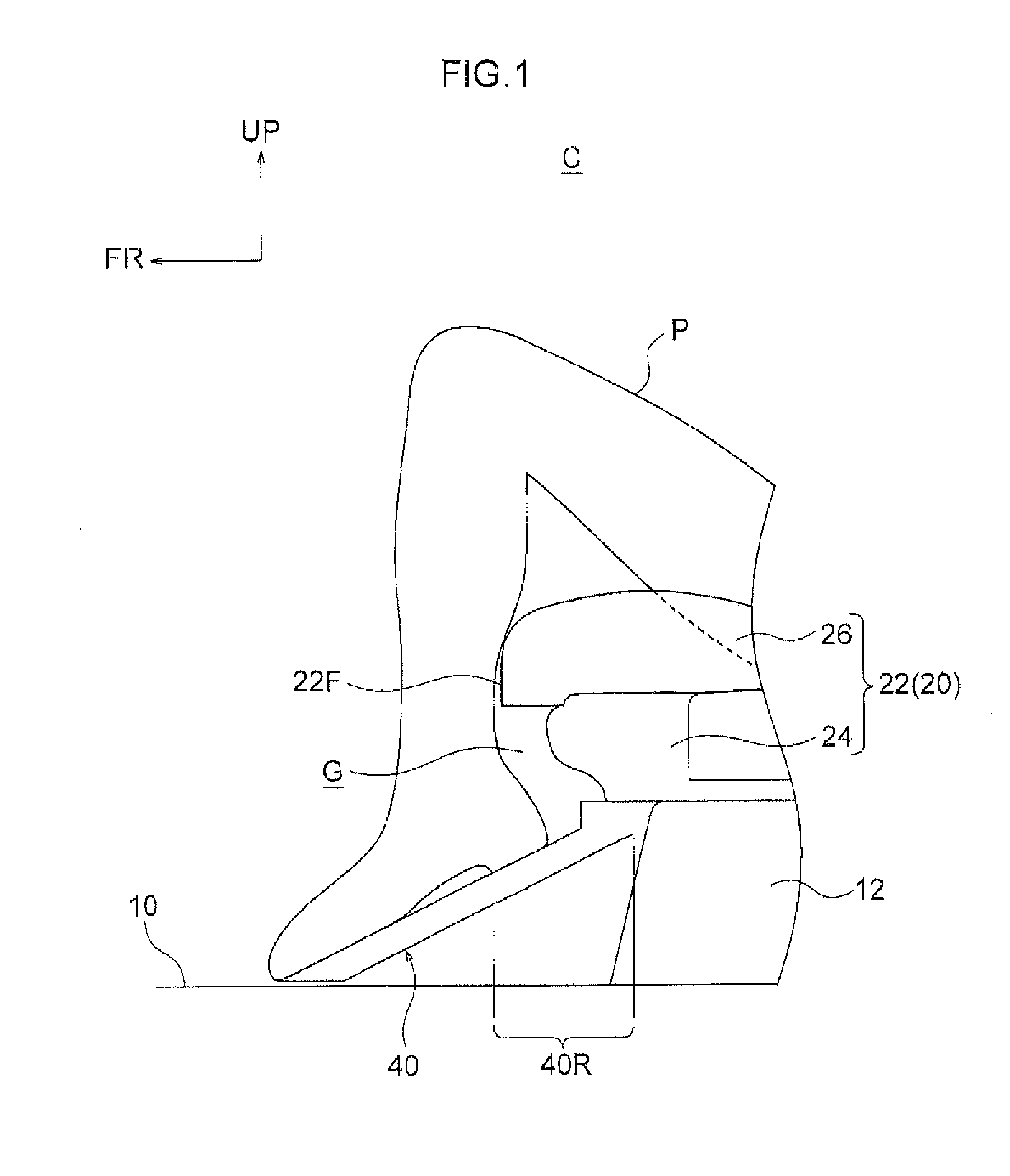
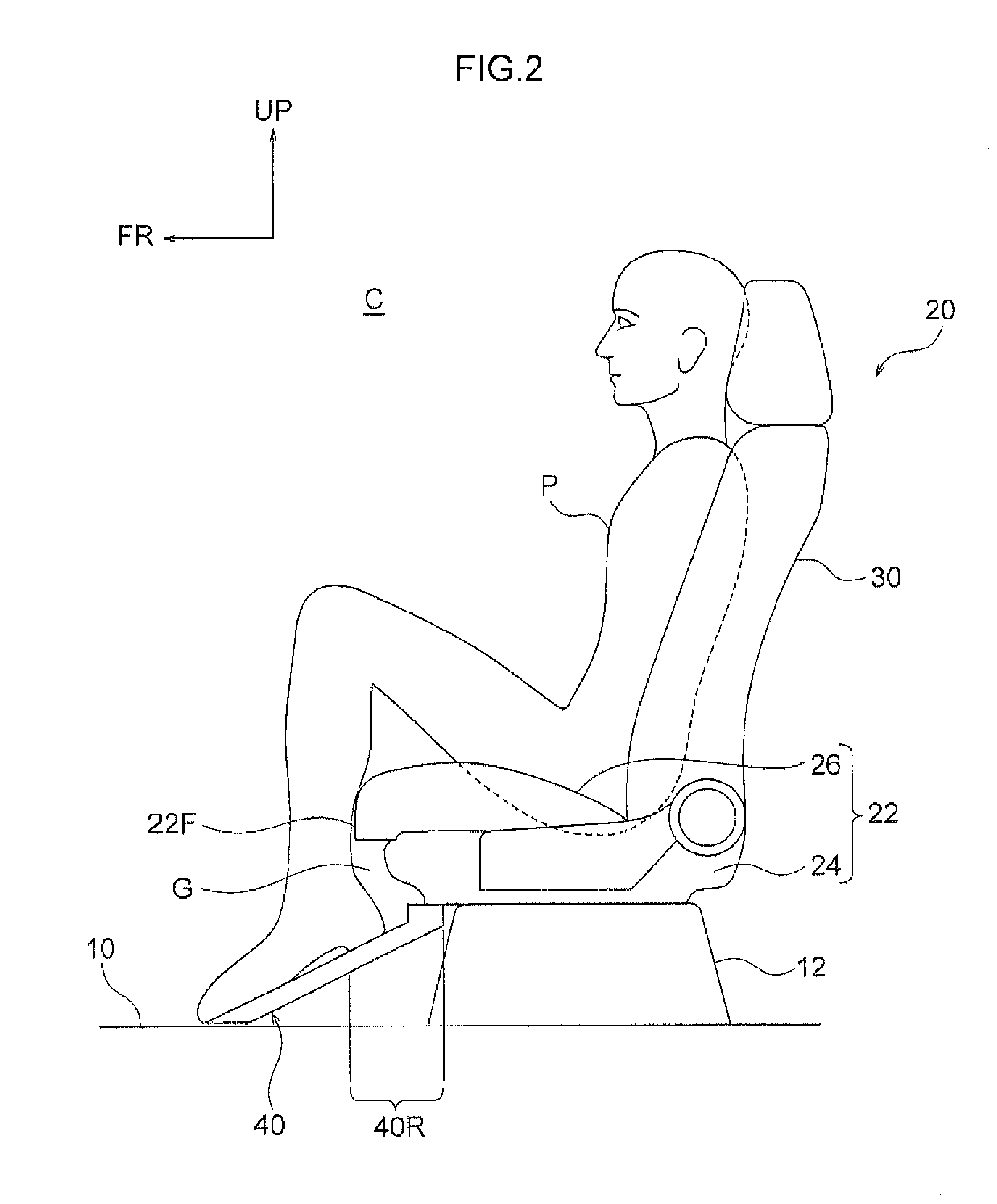
[0036]Hereinafter, a vehicle seat 20 according to a first embodiment will be described using FIG. 1 through FIG. 5B. Note that an arrow FR that is shown in the drawings indicates the vehicle front side of a vehicle (i.e., an automobile) V to which the vehicle seat 20 has been applied, while an arrow UP indicates the upper side of the vehicle, and an arrow LH indicates the vehicle left side (i.e., one side in the vehicle transverse direction). Hereinafter, firstly, the vehicle V will be described, and then the vehicle seat 20 will be described.

[0037]As shown in FIG. 3, the vehicle V is provided with an automated driving support device AD. The automated driving support device AD enables the vehicle V to be switched from manual driving to automated driving, or from automated driving to manual driving. The AD includes a microcomputer having a Central Processing Unit (CPU) and memory including ROM and RAM, and supports the automated driving mode of the vehicle based upon input informatio...

second embodiment

[0052]A vehicle seat 50 according to a second embodiment will now be described using FIG. 6 through FIG. 10. This vehicle seat 50 has the same structure as the vehicle seat 20 of the first embodiment except for the points described below. Note that the same symbols are used in the drawings for components that have the same structure as in the first embodiment.

[0053]As shown in FIG. 6, in the second embodiment, a structure is employed in which the vehicle seat 50 has a rotation motor 52, and the seat cushion 22 is rotated relative to the floor portion 10 by this rotation motor 52. The vehicle seat 50 also has a control unit 54. The control unit 54 is an electronic control unit (ECU) constituted by a microcomputer having a Central Processing Unit (CPU) and memory including ROM and RAM. The rotation motor 52 is electrically connected to the control unit 54, and the rotation motor 52 is operated (namely, the seat cushion 22 is rotated) by control performed by the control unit 54. An ope...


PUM


Abstract

A vehicle seat includes a seat cushion that is rotatably joined to a floor portion of a vehicle such that a rotation axis of the seat cushion extends vertically, the seat cushion being configured to support a buttocks of a seated vehicle occupant. The vehicle seat also includes a footrest that is joined to the seat cushion and is configured to support soles of feet of the seated vehicle occupant, the footrest being placed in a raised position in which, when seen in a seat side view, the footrest slopes rearwardly upwards such that heels of the seated vehicle occupant are raised up, and a rear portion of the footrest is placed vertically below a front end of the seat cushion.

Description

CROSS-REFERENCE TO RELATED APPLICATION[0001]This application is based on and claims priority under 35 USC 119 from Japanese Patent Application No. 2015-162499 filed on Aug. 20, 2015, the disclosure of which is incorporated by reference herein.BACKGROUND[0002]Technical Field[0003]The present disclosure relates to a vehicle seat and a vehicle.[0004]Related Art[0005]In recent years, various technologies relating to automated driving support devices for vehicles (i.e., for automobiles) have been proposed. In vehicles that are provided with these automated driving support devices, for example, one development has been to enable the front seats (i.e., both the driver's seat and the passenger's seat) to be rotated such that they face towards the rear of the vehicle, so as to create a seat layout in which the front seats and the rear seats are facing each other. For this reason, it is preferable for the vehicle seats to be constructed as rotatable seats so that the seat occupants are able t...

Claims


Application Information

Patent Timeline
IPC IPC(8): B60N2/02B60N2/44G05D1/02B60N2/14B60N2/90
CPCB60N2/0244B60N2/14B60N2002/0272B60N2/0232G05D1/021B60N2/44B60N2/143B60N3/063B60N2/0252B60N2/0256B60N2/02258B60N2/02246B60N2/0272
Inventor AKIMOTO, TAKASHI
Owner TOYOTA JIDOSHA KK
Why Eureka
Try Eureka