Blankmask and photomask for extreme ultraviolet lithography

a technology of ultraviolet light and blank mask, applied in the field of blank mask and photomask for ultraviolet light lithography, can solve the problems of increasing the probability of occurrence of footing phenomenon, fatal effect on resolution, and inability to use the existing refractive optical system of euv lithography, so as to improve the flatness of the euv blank mask, prevent oxidation and defects of the capping film, and improve the effect of flatness

Active Publication Date: 2021-05-06
S & S TECH
View PDF0 Cites 5 Cited by
  • Summary
  • Abstract
  • Description
  • Claims
  • Application Information

AI Technical Summary

Benefits of technology

[0016]The disclosure is to provide a blankmask for extreme ultraviolet lithography capable of preventing footing of an EUV photomask pattern from occurring, improving flatness of an EUV blankmask, and preventing oxidation and defects of a capping film.
[0043]According to the disclosure, the flatness of the EUV blankmask is improved, and the oxidation and defects of the capping film are prevented. In addition, the footing is prevented from occurring in the pattern of the EUV photomask manufactured by this blankmask.

Problems solved by technology

On the other hand, the EUV lithography technology may not use the existing refractive optical system such as photolithography using KrF or ArF light because EUV light is well absorbed by all materials, and a refractive index of a material at the wavelength is close to 1.
First, as the size of the pattern to be implemented is miniaturized, problems, such as distortion of the implemented pattern profile, in particular, footing of the pattern, directly affect the resolution.
In particular, the footing problem that occurs in a sub-resolution feature size (SFRS) CD pattern for correcting an optical proximity effect as well as a main pattern to be implemented has a fatal effect on the resolution.
In addition, the lower layer of the absorbing film is relatively thicker than the upper layer of the absorbing film and an etch radical component is relatively lower than a surface in a depth direction during etching, and thus there is a problem in that the probability of occurrence of the footing phenomenon increases.
Second, the following problems also occur in the flatness of the EUV blankmask.
Regarding the flatness of the absorbing film, the absorbing film is a part where the pattern is finally formed after film formation, and residual stress generated during the film formation is released while the pattern is formed, so a registration problem occurs during the release.
Recently, the registration problem for each position has emerged as a more important problem due to the size of the fine pattern.
However, in the case of forming a pattern on the current tantalum (Ta)-based absorbing film, there is no registration problem when a pattern of 10 nm or less is formed, but the registration problem due to the residual stress occurs when a pattern of 7 nm or less is formed.
Moreover, the registration problem has a more fatal effect on the EUV lithography in which exposure light is obliquely incident at an incident angle of 6°.
The problem of the flatness of the capping film including the reflection film is related to the stress of a thin film.
Since the EUV exposure light is inclined at 6° and is transferred to a wafer PR through a reflection path, when the flatness of the capping film including the reflection film is high, a difference between an ideal reflection path and an actual reflection path occurs, and thus a pattern position error occurs in the transferred pattern.
Accordingly, there is a problem in that the path of the actual reflected light has a larger difference from the path of the ideal reflected light, and thus the problem of the pattern position error gets worse.
Third, a ruthenium (Ru)-based material forming the capping film causes the following problems.
However, the ruthenium (Ru)-based material is oxidized by a cleaning solution such as ozone water and DI-water, and ruthenium (Ru) of the capping film and silicon (Si) of the reflection film under the capping film are oxidized due to high energy during the repetitive exposure to the wafer.
Accordingly, damage to the capping film occurs, resulting in decreasing reflectivity to the exposure light, increasing a defect occurrence rate, and adversely affecting the thin film (absorbing film, phase-shift film, or the like) on the capping film.

Method used


Image

  • Blankmask and photomask for extreme ultraviolet lithography
  • Blankmask and photomask for extreme ultraviolet lithography

Examples


Embodiment Construction

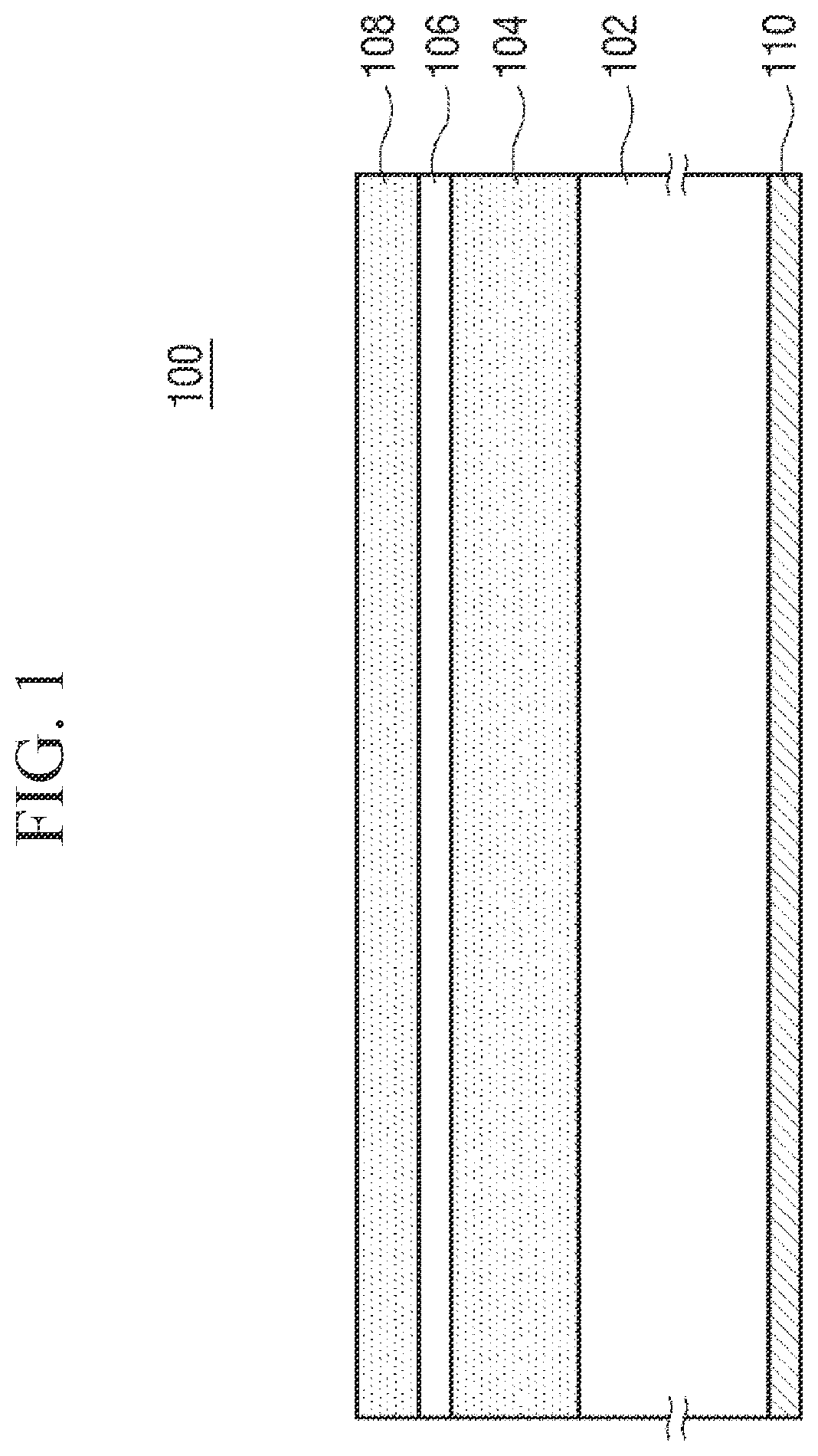
[0047]FIG. 1 is a cross-sectional view illustrating a blankmask for extreme ultraviolet lithography according to the disclosure.

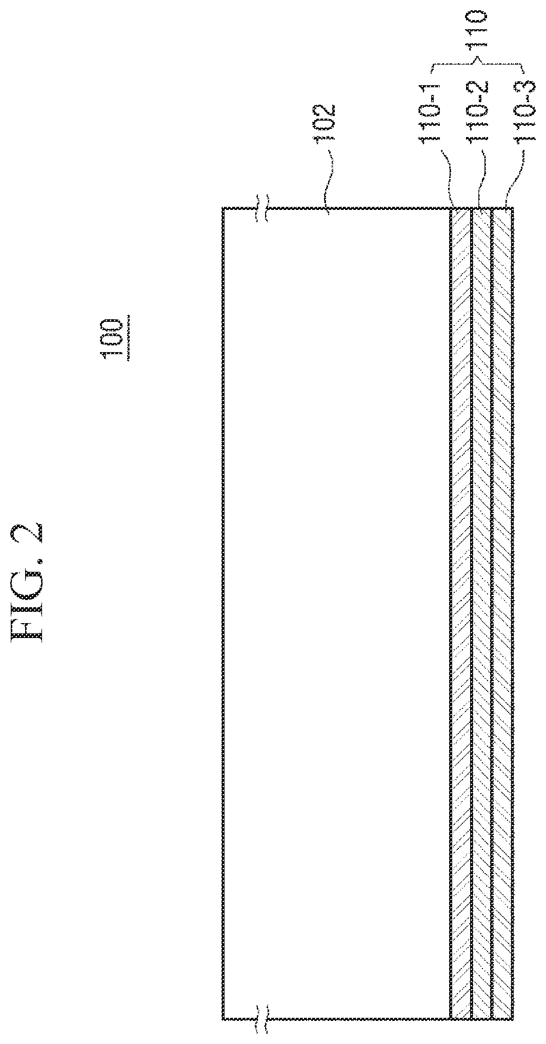
[0048]Referring to FIG. 1, a blankmask 100 for extreme ultraviolet lithography according to the disclosure includes a transparent substrate 102 and a reflection film 104, a capping film 106, and an absorbing film 108 that are sequentially stacked on the transparent substrate 102. In addition, the blankmask 100 includes a conductive film 110 provided on a rear surface of the transparent substrate 102.

[0049]The transparent substrate 102 is a glass substrate for a reflective blankmask using EUV exposure light of 13.5 nm, and preferably uses a low thermal expansion material (LTEM) substrate having a low coefficient of thermal expansion in a range of 0±1.0×10⁻⁷ / ° C., and preferably 0±0.3×10⁻⁷ / ° C. in order to prevent deformation of a pattern due to heat and stress due to a thin film during exposure. To this end, the transparent substrate 102 may be made of a mat...


PUM

PropertyMeasurementUnit
surface roughnessaaaaaaaaaa
thicknessaaaaaaaaaa
temperatureaaaaaaaaaa

Abstract

A blankmask for extreme ultraviolet lithography includes a reflection film, a capping film, and an absorbing film that are sequentially formed on a transparent substrate, in which the reflection film has a surface roughness of 0.5 nm Ra or less. It is possible to prevent footing of an EUV photomask pattern from occurring, improving flatness of an EUV blankmask, and prevent oxidation and defects of a capping film.

Description

CROSS-REFERENCE TO RELATED APPLICATION[0001]This application is based on and claims priority under 35 U. S. C. § 119 to Korean Patent Application No. 10-2019-0140110, filed on Nov. 5, 2019, the disclosure of which is herein incorporated by reference in its entirety.BACKGROUND1. Field[0002]The disclosure relates to a blankmask and photomask for extreme ultraviolet lithography, and more particularly, to blankmask and photomask for extreme ultraviolet lithography capable of implementing a fine pattern of 14 nm or less, particularly, 10 nm or 7 nm or less using extreme ultraviolet (EUV) light of 13.5 nm as exposure light.2. Discussion of Related Art[0003]Recently, lithography technology for manufacturing semiconductor is evolving from ArF, ArFi, and multiple (MP) lithography technologies to EUV lithography technology. The EUV lithography technology is technology that is in the limelight for manufacturing semiconductor devices of 10 nm or less because the EUV lithography enables resoluti...

Claims


Application Information

Patent Timeline
Patent Type & Authority Applications(United States)
IPC IPC(8): G03F1/24G03F1/58G03F1/20H01L21/033
CPCG03F1/24G03F1/58H01L21/0337H01L21/0332G03F1/20G03F1/50G03F1/52G03F1/38G03F1/48G03F7/2004G03F1/54G03F7/70033G03F7/2008G03F7/38
Inventor SHIN, CHEOLLEE, JONG-HWAYANG, CHUL-KYUKONG, GIL-WOOSEO, GYEONG-WON
Owner S & S TECH
Why Eureka
Try Eureka