
Glass substrate and method for manufacturing the same, cover glass and method for manufacturing the same, personal digital assistant, and display device

a technology of glass substrate and cover glass, which is applied in the direction of coatings, instruments, other domestic objects, etc., can solve the problems of sensor sensitivity decline, uneven capacitance between the sensor electrode and the detection object, and uneven so as to achieve satisfy the surface appearance of the cover glass. , the effect of good flatness of the thin portion

Active Publication Date: 2016-12-08
ASAHI GLASS CO LTD
View PDF7 Cites 71 Cited by
  • Summary
  • Abstract
  • Description
  • Claims
  • Application Information

AI Technical Summary

Benefits of technology

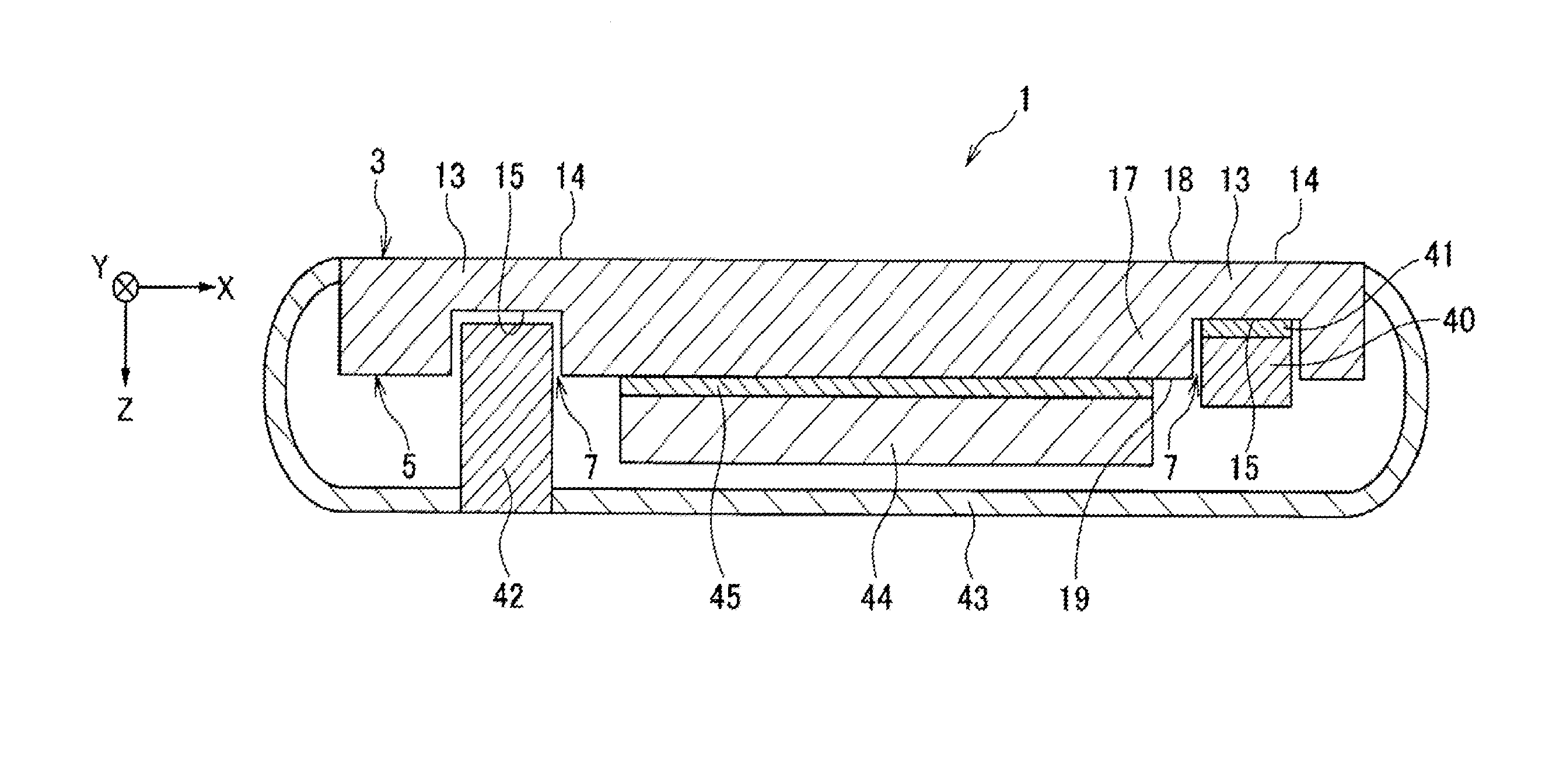
The present invention provides a cover glass that can be used for a sensor and display device. The glass has excellent visibility with a low haze value in the thin portion, which satisfies both the flatness and surface appearance of the glass. When a sensor is placed in the concave position, the glass ensures good sensitivity. The invention also includes a simple method for manufacturing the cover glass and substrate.

Problems solved by technology

However, even if a capacitance sensor is arranged in the concave portion in the cover glass for a mobile device of Patent Document 1, it may cause some inconvenience since the haze value and surface roughness Ra of the concave portion are large.
Specifically, since the surface of the concave portion is rough, the distance between the sensor electrode and the detection object varies and the capacitance to be detected becomes also uneven.
In this case, there is a probability that the sensor sensitivity lowers and the sensor could not exhibit the desired function.
Further, since the haze value and surface roughness Ra of the concave portion are large, the concave portion is noticeable and loses unity with the flat portion of the main surface, therefore causing disfigurement of the cover glass as a whole.
In addition, in the case where a display panel is arranged in the concave portion, when it is attached with an adhesive, the surface roughness on the concave portion may be large and a void may be formed, and the visibility of images may be deteriorated.
In the manufacturing method of Patent Document 2, a resist mask that reflects the outward form of plural cover glasses must be prepared, and the mask preparation step is troublesome.
In addition, the cutting step of obtaining plural cover glasses from a sheet glass requires etching, and therefore the time for the cutting step is prolonged and the step causes cost increase for etchant disposal.

Method used


Image

  • Glass substrate and method for manufacturing the same, cover glass and method for manufacturing the same, personal digital assistant, and display device
  • Glass substrate and method for manufacturing the same, cover glass and method for manufacturing the same, personal digital assistant, and display device
  • Glass substrate and method for manufacturing the same, cover glass and method for manufacturing the same, personal digital assistant, and display device

Examples


example 1

[0269]An example of the glass substrate 101 shown in FIG. 8 and its manufacturing method is described. A glass member 201 (see FIG. 11) having a length in the direction X of 730 mm, a length in the direction Y of 920 mm and a thickness in the direction Z of 0.5 mm was used. In the glass member 201, 65 concave portions 207 in total, concretely 5 lines in the direction X at a pitch of 130 mm and 13 rows in the direction Y at a pitch of 65 mm were formed (see FIG. 12). The size of the concave portion 207 was 5 mm in length in the direction X, 13 mm in length in the direction Y and 0.27 mm in depth in the direction Z. Specifically, the thickness in the direction Z of the thin part formed by providing the concave portions 207 was 0.23 mm.

[0270]The method for forming the concave portions 207 in the front surface 203 or the back surface of the glass member 201 is as follows. First, a resist material was applied to the front surface 203 or the back surface of the glass member 201, holes hav...

example 2

[0274]An example of the glass substrate 101 and its manufacturing method is described. This differs from Example 1 in that an aluminosilicate glass manufactured by Asahi Glass Co., Ltd., Dragontrail-X, was used as the glass member 201, and that the shape of the concave portion 207 was a circular shape having a diameter of 10 mm. In addition, after the glass member 201 was taken out from the hydrofluoric acid (HF) solution after etching, this was kept as such for 30 seconds and thereafter the resist materials (the first mask member 301 and second mask member 401) were peeled away, and then this was washed. In the same manner as in Example 1 except these points, a glass substrate 101 was produced.

[0275]The side surface of the concave portion 107 had a curved shape smoothly connecting to the bottom of the concave portion 107, and the radius of curvature from the bottom of the concave portion toward the side surface thereof was at most 0.4 mm. The connecting part between the side surfac...

example 3

[0276]An example of the cover glass 1 and its manufacturing method is described. The glass substrate 101 of Example 1 or 2 was cut into rectangular pieces in a size of 130 mm×65 mm each having one concave portion 107, using a wheel cutting device for glass cutting. Accordingly, plural rectangular cover glasses 1 each having one concave portion 107 in the back surface thereof were obtained. In cutting, the second mark 122 was read and the cutting position was determined. For securing correct cutting, it was confirmed whether the cutting line could run through the center of the first mark 121, from which correct cutting in the predetermined shape was confirmed. The second mark 122 and the concave portion 107 have a correlation with each other in point of the position thereof, and therefore the concave portion 107 was arranged at the desired position of 130 mm×65 mm.

[0277]As shown in FIG. 30A, the four corners 2 of the rectangular cover glass 1, in a plan view thereof, were cut with CN...


PUM

PropertyMeasurementUnit
hazeaaaaaaaaaa
arithmetic mean roughnessaaaaaaaaaa
hazeaaaaaaaaaa

Abstract

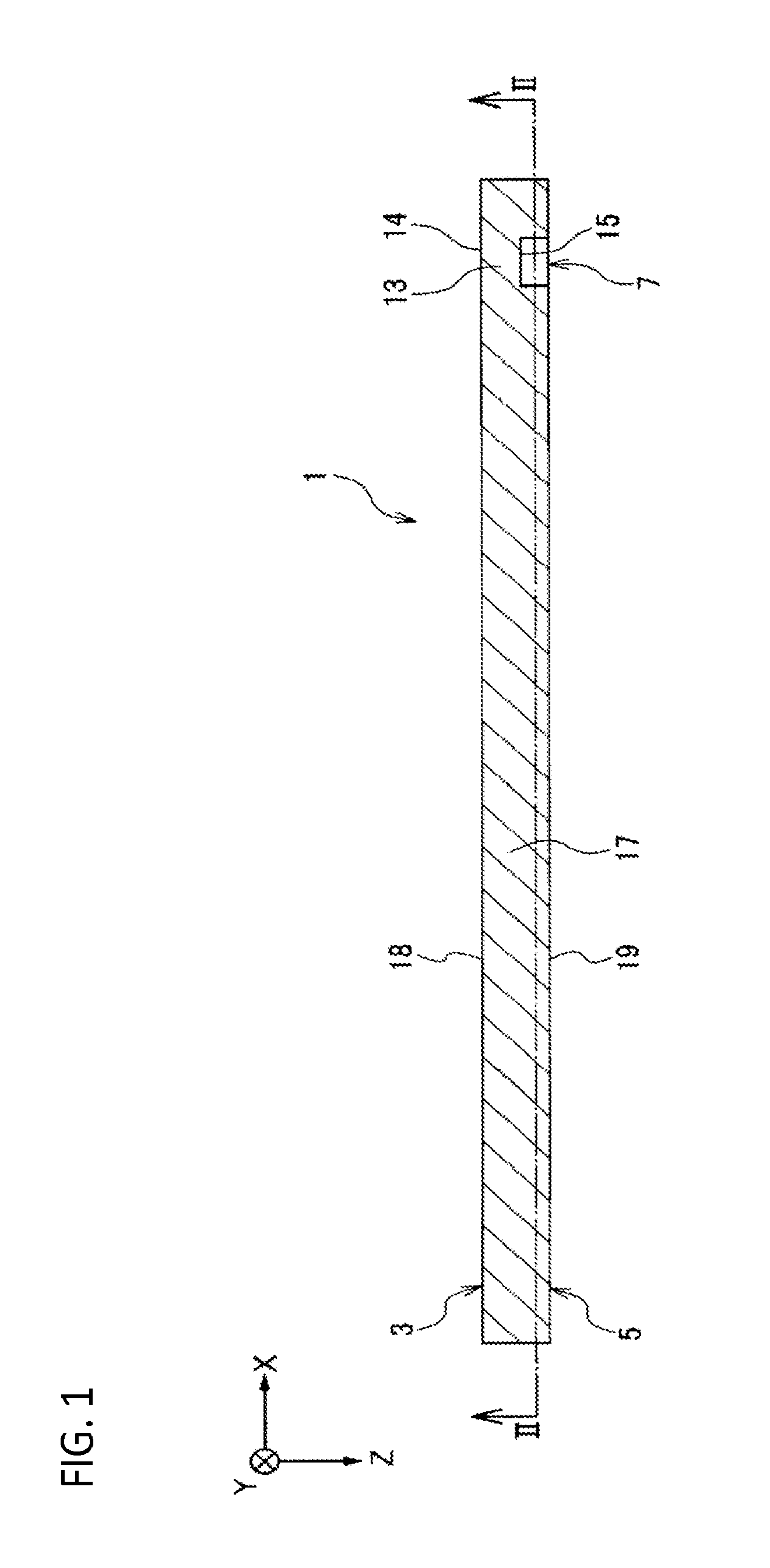
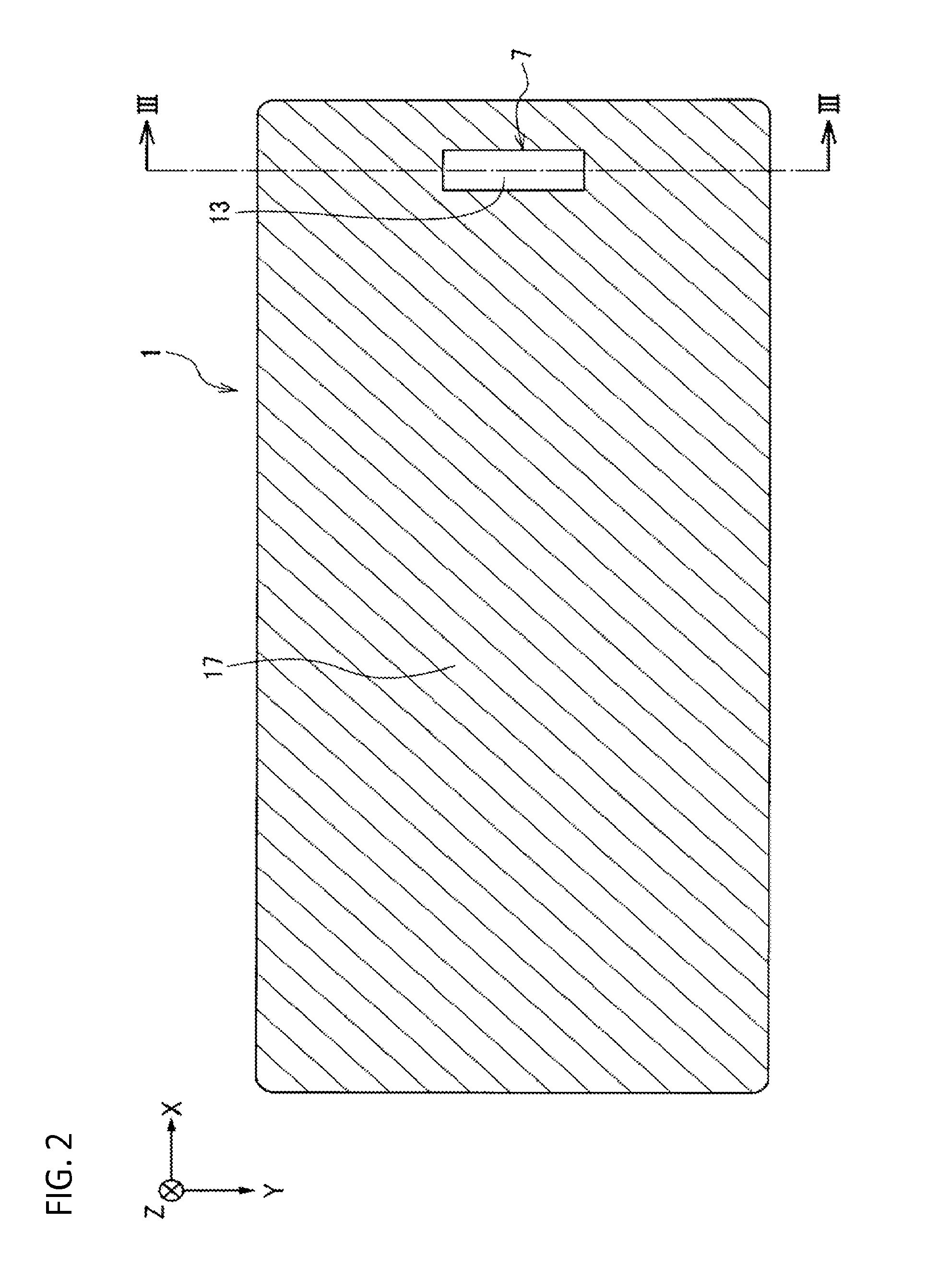
In a glass substrate for extracting therefrom a plurality of cover glasses to protect a protection object, plural concave portions are provided in a front surface or back surface of the glass substrate. The glass substrate includes plural thin portions formed by providing the plural concave portions and a thick portion connecting to the thin portion, and a haze value of the thin portion is 8% or less.

Description

CROSS-REFERENCE TO RELATED APPLICATIONS[0001]This application claims priority from Japanese Patent Application No. 2015-115138 filed on Jun. 5, 2015 and Japanese Patent Application No. 2016-104656 filed on May 25, 2016, the entire subject matter of which is incorporated herein by reference.BACKGROUND OF THE INVENTION[0002]Technical Field[0003]The present invention relates to a glass substrate and a method for manufacturing the same, a cover glass and a method for manufacturing the same, a personal digital assistant, and a display device.[0004]Background Art[0005]Recently, as an advanced security measure for electronic apparatuses, a method of using a fingerprint for personal authentication has been actively used. Examples of the fingerprint authentication method include an optical type sensor, a heat-sensitive type sensor, a pressure-sensitive type sensor, a capacitance type sensor and an ultrasonic type sensor. From the viewpoint of sensitivity and power consumption, a capacitance ...

Claims


Application Information

Patent Timeline
Patent Type & Authority Applications(United States)
IPC IPC(8): G06F3/041G06F3/043B32B3/02C03C15/00B32B3/10
CPCG06F3/0412C03C15/00B32B3/10B32B2457/208G06F3/0433B32B2307/412B32B3/02C03C17/002G06V40/13B32B17/06H04M1/0266G06F2203/04103H04M2250/12C03C3/076C03C3/078C03C3/085C03C17/00C03C21/002C03C2218/119
Inventor OZEKI, MASAOTADA, MASAHIKOSANO, MAKOTOTAITO, OSAMI
Owner ASAHI GLASS CO LTD
Learn More