Vehicle seat air-conditioner

a technology for vehicle seats and air conditioners, which is applied in vehicle heating/cooling devices, seat heating/ventilation devices, vehicle arrangements, etc., can solve the problems of large heat loss, passenger sitting on the vehicle seat, and so as to avoid blowing insufficiently temperature controlled air

Inactive Publication Date: 2016-09-01
DENSO CORP
View PDF4 Cites 14 Cited by
  • Summary
  • Abstract
  • Description
  • Claims
  • Application Information

AI Technical Summary

Benefits of technology

[0005]When starting seat air-conditioning, there is a large amount of heat loss in a ventilation passage from a heat exchanger, which heats or cools air, to an air outlet. Accordingly, the blowout air is insufficiently temperature controlled. Due to this, there is a concern that a passenger, who is sitting on the vehicle seat and is being blown by this blowout air, may be discomforted. In this regard, according to the vehicle seat air-conditioner of Patent Literature 1, the insufficiently conditioned air is blown weakly, so as to reduce the discomfort of the passenger.
[0007]In view of the above points, it is an object of the present disclosure to provide a vehicle seat air-conditioner capable of maintaining the comfort of a passenger seated on the vehicle seat, without needing to suppress a blowout airflow rate when starting air-conditioning.
[0009]According to the first aspect, the controller causes the first switching device to switch the air blowout portion to the first blowing state when the air blown from the air blowout portion is in the pre-temperature controlled state, and causes the first switching device to switch the air blowout portion to the second blowing state when the air blown from the air blowout portion is in the temperature controlled state. Accordingly, it is possible to avoid blowing insufficiently temperature controlled air against a seated occupant, without having to suppressed the blowout airflow rate when starting air-conditioning. For this reason, the comfort of a passenger sitting on the vehicle seat may be maintained.

Problems solved by technology

When starting seat air-conditioning, there is a large amount of heat loss in a ventilation passage from a heat exchanger, which heats or cools air, to an air outlet.
Accordingly, the blowout air is insufficiently temperature controlled.
Due to this, there is a concern that a passenger, who is sitting on the vehicle seat and is being blown by this blowout air, may be discomforted.
However, according to the vehicle seat air-conditioner of Patent Literature 1, during the period that the blowout air is insufficiently temperature controlled, the airflow rate of the air passing through the ventilation passage is low.
For this reason, there is a concern that the temperature of ventilation passage may not readily reach the temperature of the air flowing through the ventilation passage.
As such, there is a concern that a longer amount of time may be needed for the air temperature blown against the passenger to reach a sufficiently temperature controlled temperature.

Method used


Image

  • Vehicle seat air-conditioner
  • Vehicle seat air-conditioner
  • Vehicle seat air-conditioner

Examples


first embodiment

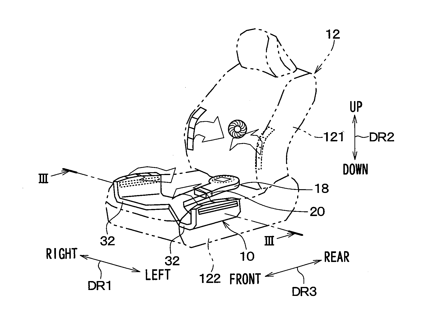
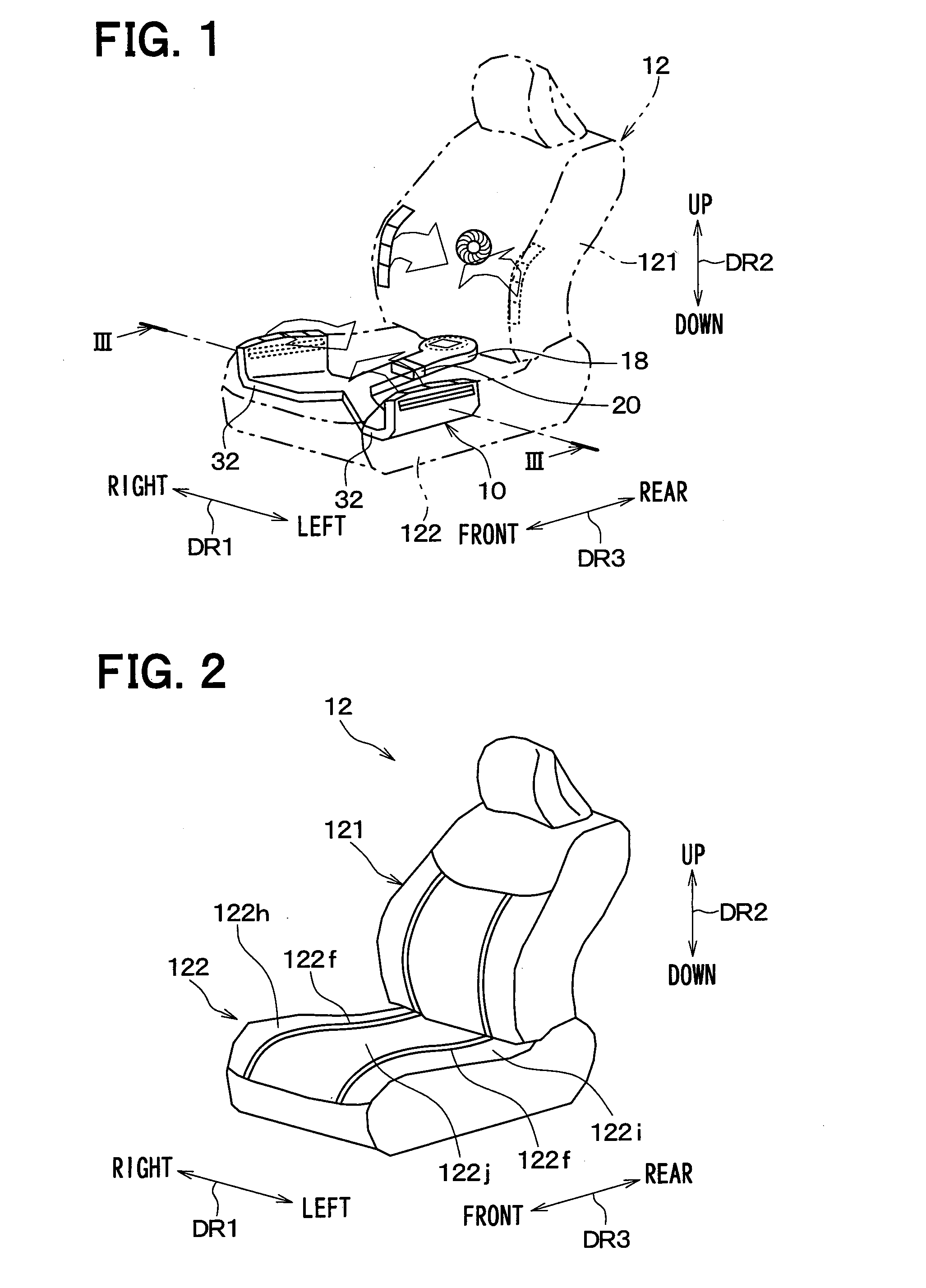
[0030]FIG. 1 is an outline perspective view showing a vehicle seat air-conditioner 10 of the present embodiment, and showing a vehicle seat 12 having the vehicle seat air-conditioner 10 installed. Each of a seat back 121 and a seat cushion 122 of the vehicle seat 12 has a vehicle seat air-conditioner installed. The vehicle seat air-conditioner 10 of the present disclosure (hereinafter, simply “seat air-conditioner 10”) is a vehicle seat air-conditioner installed in the seat cushion 122. Further, in FIG. 1, the directional market DR1 shows a left-right direction DR1 of the vehicle, i.e., is a vehicle width direction DR1. The directional market DR2 shows an up-down direction DR2 of the vehicle, i.e., is a vehicle vertical direction DR2. The directional market DR3 shows a front-rear direction of the vehicle, i.e., is a vehicle longitudinal direction DR3

[0031]The vehicle seat 12 shown in FIG. 1 includes the seat back 121 and the seat cushion 122. A passenger sitting on the vehicle seat ...

second embodiment

[0060]Next, a second embodiment of the present disclosure will be explained. The explanation will be focused on the points of the present embodiment which differ from the previously described first embodiment. Further, explanations of portions which are the same as, or equal to, the previous embodiment will be omitted or simplified. The same applies the third embodiment and onward, described later.

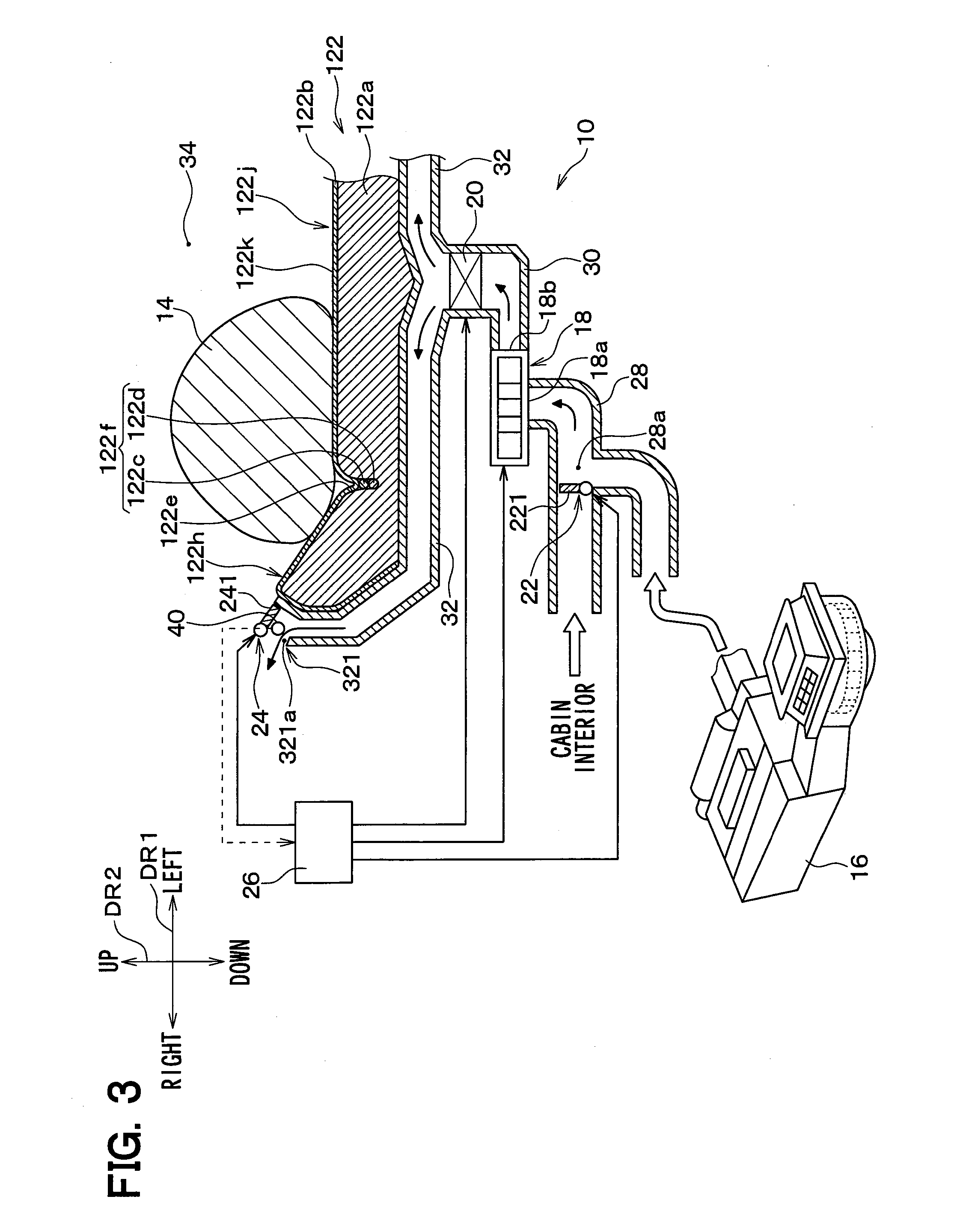
[0061]FIG. 6 is a cross sectional view of the seat air-conditioner 10 and the seat cushion 122 of the present embodiment, and corresponds to FIG. 3 of the first embodiment. FIG. 7 is a cross sectional view of the seat air-conditioner 10 and the seat cushion 122 of the present embodiment, and corresponds to FIG. 4 of the first embodiment. FIG. 7 is different from FIG. 6 in that the orientation of an air guide member 242 of the blowout air switching device 24 is different.

[0062]As shown in FIGS. 6 and 7, the blowout ventilation pipe 32 of the present embodiment does not wrap around the sides...

third embodiment

[0067]Next, a third embodiment of the present disclosure will be explained. The explanation will be focused on the points of the present embodiment which differ from the previously described first embodiment.

[0068]FIG. 8 is a cross sectional view of the seat air-conditioner 10 and the seat cushion 122 of the present embodiment, and corresponds to FIG. 3 of the first embodiment. FIG. 9 is a cross sectional view of the seat air-conditioner 10 and the seat cushion 122 of the present embodiment, and corresponds to FIG. 4 of the first embodiment. FIG. 8 is different from FIG. 9 in that the orientation of an opening and closing door 243 of the blowout air switching device 24 is different.

[0069]As shown in FIGS. 8 and 9, the blowout ventilation pipe 32 of the present embodiment does not wrap around the sides of the seat cushion 122, and the blowout ventilation pipe 32 does not have the air blowout portion 321 (refer to FIG. 3). An end portion 322 of the blowout ventilation pipe 32, which i...


PUM


Abstract

A controller causes a blowout air switching device to switch an air blowout portion to a first blowing state if air blown from the air blowout portion is in a pre-temperature controlled state. If air blown from the air blowout portion is in a temperature controlled state, the controller causes the blowout air switching device to switch the air blowout portion to a second blowing state. Furthermore, in the first blowing state, a first air outlet is opened while a second air outlet is closed. Conversely, in the second blowing state, the first air outlet is closed while the second air outlet is open. Thus, it is possible to avoid blowing insufficiently temperature controlled air against a seated occupant, without having to suppressed the blowout airflow rate when a seat air-conditioner starts air-conditioning.

Description

CROSS-REFERENCE TO RELATED APPLICATION[0001]The present application is based on Japanese patent application No. 2013-222118 filed on Oct. 25, 2013, the content of which is incorporated herein by reference.TECHNICAL FIELD[0002]The present disclosure relates to a vehicle seat air-conditioner that blows out conditioned air in a vehicle seat.BACKGROUND ART[0003]As a conventional technology related to vehicle seat air-conditioners, for example Patent Literature 1 discloses a vehicle seat air-conditioner that blows out conditioned air from a plurality of micro holes formed on a seat surface. According to the vehicle seat air conditioner of Patent Literature 1, when starting seat air-conditioning while the vehicle cabin interior is being cooled down or warmed up, a blowout airspeed from the seat surface is limited such that the blowout airspeed is 0.4 m / s or lower.PRIOR ART LITERATUREPatent Literature[0004]Patent Literature 1: JP 2001-307731 ASUMMARY OF THE INVENTION[0005]When starting sea...

Claims


Application Information

Patent Timeline
Patent Type & Authority Applications(United States)
IPC IPC(8): B60H1/00B60N2/56
CPCB60H1/00285B60H1/00842B60N2/5657B60H1/00871B60H1/00564B60H1/00678B60H2001/003B60N2/5628
Inventor TANAKA, YUUSUKENIIMI, YASUHIKOFUJII, TAKAHISA
Owner DENSO CORP
Why Eureka
Try Eureka