Pressure cooker

a pressure cooker and pressure cooker technology, applied in the field of temperature-regulated cookware and servingware items, can solve the problems of unsuitable thermometers, increased pressure within the pot, and much higher steam heat transfer potential, and achieve high thermal conductivity and accurate temperature readings.

Inactive Publication Date: 2011-05-03
IMURA INT INC
View PDF22 Cites 73 Cited by
  • Summary
  • Abstract
  • Description
  • Claims
  • Application Information

AI Technical Summary

Benefits of technology

[0010]In a preferred embodiment the heatable object is a sealed object such as a pressure cooker. In the embodiment in which the temperature sensor extends through the wall of the cooker, the head of the temperature sensor is inserted through the tunnel in the body of the cooker from the outer surface so as to be generally flush with the inner surface of the wall of the body. A sealing cap is then positioned and crimped over (or otherwise connected to or in close contact with) the head of the sensor. In an alternative embodiment, the sealing cap is an integral part of the temperature sensor, and the sensor is inserted through the tunnel in the body of the cooker from the inner surface toward the exterior surface. The tunnel and the sealing cap may also include a potting material to surround the sensor. The sealing cap may be in the form of a screw, rivet or a plug that includes a cylindrical member that fits within the tunnel and in which the head of the temperature sensor fits, and that also includes a head that has a diameter greater than the diameter of the tunnel to fully cover the tunnel and formed to fit to the interior surface of the cooker body wall closely. The sealing cap and potting material combine to seal the tunnel and prevent air and / or liquid from escaping the interior of the cooker during pressurized cooking.
[0011]The sealing cap of the instant invention is made of a material having a high thermal conductivity, such as a conductive silicon, metal or other suitable material. The highly conductive material allows the temperature sensor to obtain a highly accurate temperature reading for the interior of the object.
[0014]The RFID tag is located within a cavity formed in the handle of the object of the instant invention to position the tag outside of the heat-generation zone for the object. This reduces the temperature to which the tag is subjected, maximizing the life of the tag. The handle holds the RFID tag parallel to the cook-top surface for maximum signal strength during operation.

Problems solved by technology

Such thermometers are undesirable for use with cookware / servingware objects that have a lid as the use of a probe-type thermometer requires removal of the lid each time a temperature reading is taken.
The steam is trapped within the pressure cooker by the sealed lid, causing the pressure within the pot to increase.
In addition, steam has a much higher heat transfer potential than a liquid at the same temperature, further decreasing cooking time.
Maintaining a constant temperature and pressure within pressure cooker 10 is often difficult to do manually, taking a considerable amount of trial and error in adjusting the stove temperature.
As the pressure within the pressure cooker is proportional to the temperature, even minor inaccuracies in the temperature measurement can be critical and result in overcooking or undercooking.

Method used


Image

  • Pressure cooker
  • Pressure cooker
  • Pressure cooker

Examples


Embodiment Construction

[0021]As required, a detailed embodiment of the present inventions is disclosed herein; however, it is to be understood that the disclosed embodiment is merely exemplary of the principles of the invention, which may be embodied in various forms. Therefore, specific structural and functional details disclosed herein are not to be interpreted as limiting, but merely as a basis for the claims and as a representative basis for teaching one skilled in the art to variously employ the present invention in virtually any appropriately detailed structure.

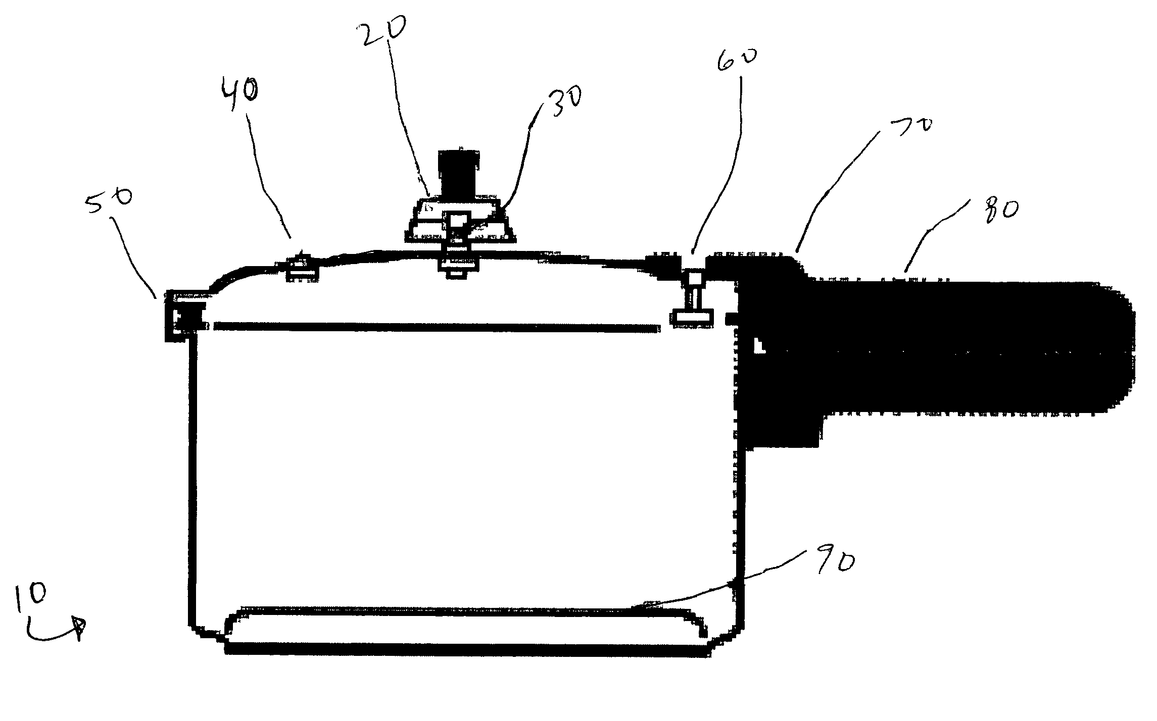
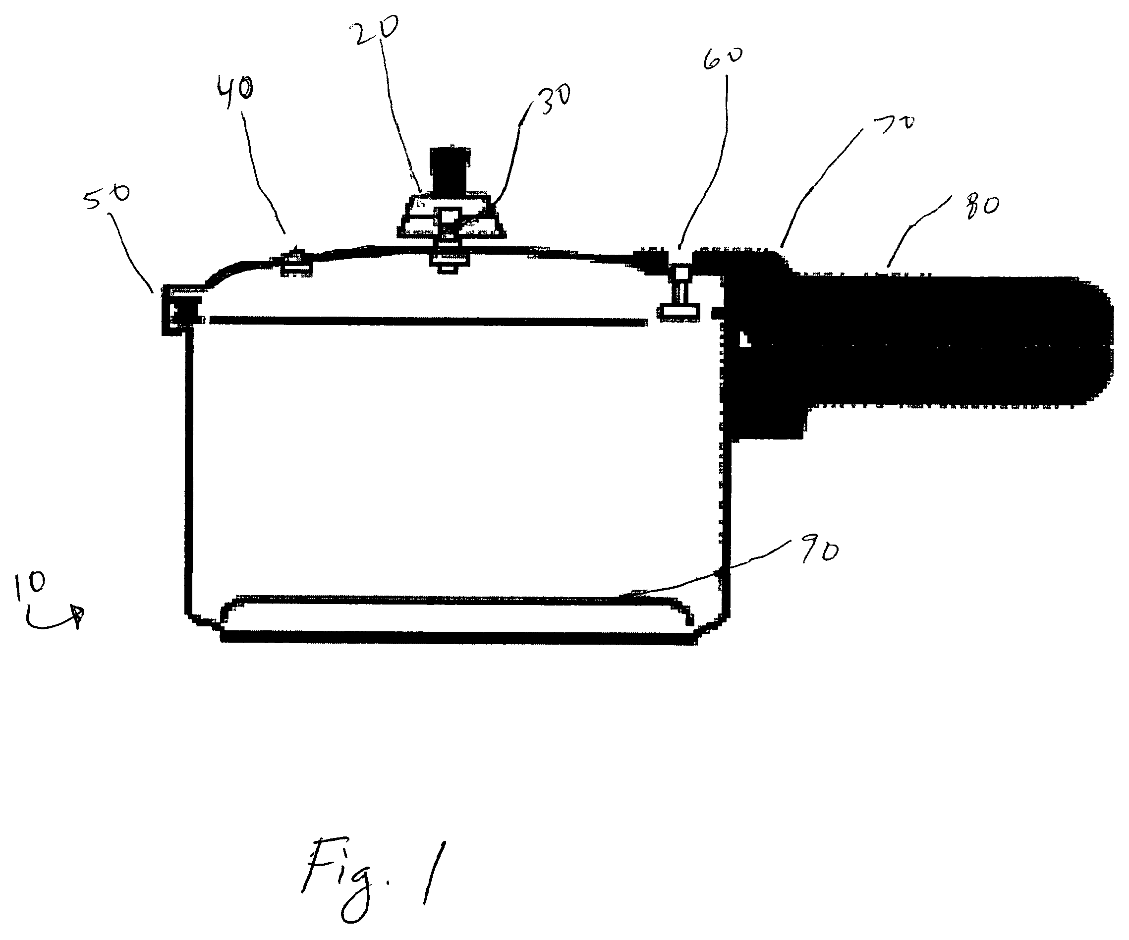
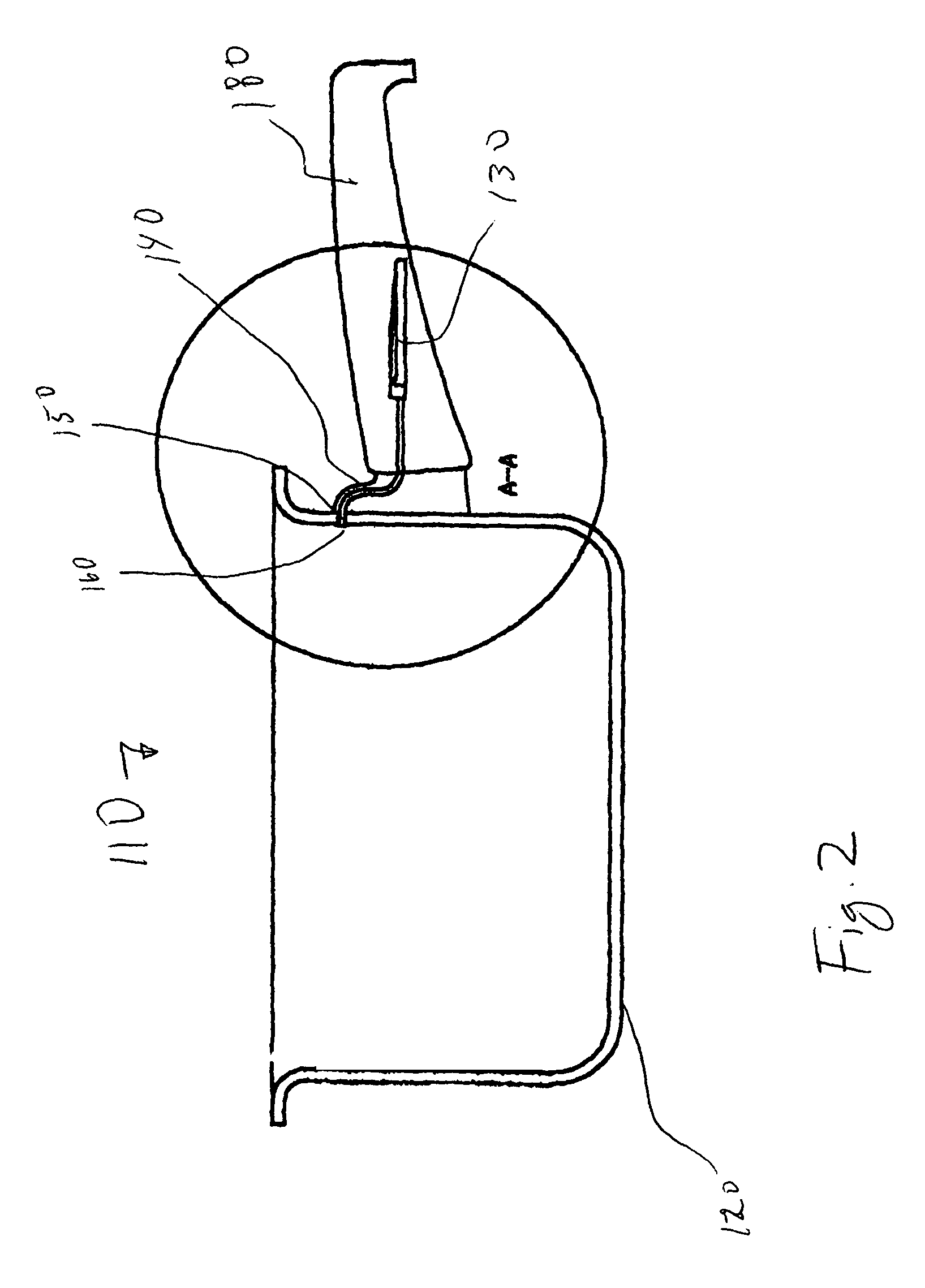
[0022]Referring to FIGS. 2 and 3, a pressure cooker in which a temperature sensor extends through the wall of the cooker is shown. As is shown in FIG. 2, pressure cooker 110 includes heatable body 120, handle 180 in which RFID tag 130 is located, and temperature sensor 150 located within a tunnel that passes through the wall of body 120. Temperature sensor 150 is connected to RFID tag 130 by conductors 140, and includes sealing cap 160 positi...


PUM


Abstract

A sealed cookware and servingware object, such as a pressure cooker, is provided. The object is temperature and pressure regulated using control technology such as Radio Frequency Identification (RFID) technology and temperature sensors associated with the objects. In a first embodiment, the temperature sensor is at least partially embedded in the base of the object. In a second embodiment, the temperature sensor extends through a tunnel in a wall of the object and includes a sealing cap to cover the tunnel and prevent air and / or liquid from escaping the interior of the object.

Description

CROSS-REFERENCE TO RELATED APPLICATIONS[0001]This application claims priority pursuant to 35 U.S.C. 119(e) to co-pending U.S. Provisional Patent Application Ser. No. 60 / 624,834, filed Nov. 3, 2004, the entire disclosure of which is incorporated herein by reference. This application is a continuation-in-part of U.S. application Ser. No. 10 / 833,356 filed Apr. 28, 2004 now U.S. Pat. No. 7,157,675, the disclosures of which is incorporated herein by reference in its entirety.FIELD OF THE INVENTION[0002]The present invention is broadly concerned with temperature regulated cookware and servingware items, such as pots, pans, buffet serving pans, serving dishes, platters, and the like. More particularly, the invention is concerned with sealed cookware and servingware objects, such as pressure cookers, that are temperature and pressure regulated using control technology such as Radio Frequency Identification (RFID) technology and temperature sensors associated with the objects.BACKGROUND OF T...

Claims


Application Information

Patent Timeline
Patent Type & Authority Patents(United States)
IPC IPC(8): H05B6/12H05B6/66
CPCA47J27/0802
Inventor IMURA, MAMORU
Owner IMURA INT INC
Why Eureka
Try Eureka