Chip overheating protection

a technology of overheating protection and chips, applied in the direction of heat measurement, instruments, digital computer details, etc., can solve the problems of increasing the heat generated by the chip per given area, reducing the feature size, and reducing so as to reduce or minimize the involvement of the host and minimize the required involvemen

Inactive Publication Date: 2011-05-03
AVAGO TECH INT SALES PTE LTD
View PDF8 Cites 8 Cited by
  • Summary
  • Abstract
  • Description
  • Claims
  • Application Information

AI Technical Summary

Benefits of technology

[0007]Embodiments of the present invention are directed to systems and methods for controlling the temperature of an internal device while reducing or minimizing the involvement of the host. Accordingly embodiments of the present invention provide for offloading some of the heat monitoring and remediation work to the actual device itself, thus minimizing the required involvement of the host. Some embodiments provide for the device to monitor its own temperature and, in the event of high temperature, perform device specific heat reduction actions without involving the host.

Problems solved by technology

However, placing more and more features in a small area increases the heat generated by the chip per given area, because the power consumed by transistors usually does not decrease at the same rate as their size.
This problem is worsened by the fact that decreasing the feature size often comes with a tradeoff of increased leakage current which also produces heat.
Decreasing the size of a computer, or increasing the density of computing devices (e.g., blade servers) often reduces and / or removes various air channels and vents from it, thus decreasing its ability to remove heat from its internal components.
The above issues cause some concern for temperature management of the various devices within a computer.
While using a fan is beneficial for most devices it may cause problems for devices that need to be on at all times, such as devices that are a part of networked storage servers, web servers, etc.
Keeping a fan on at all times will severely shorten the life of the fan, and thus of the device.
However these prior art system require constant periodic interruptions of the computer's main CPU for the purpose of monitoring the temperatures of connected devices.
These interruptions may significantly affect the computer's overall performance.

Method used


Image

  • Chip overheating protection
  • Chip overheating protection
  • Chip overheating protection

Examples


Embodiment Construction

[0015]In the following description of preferred embodiments, reference is made to the accompanying drawings which form a part hereof, and in which it is shown by way of illustration specific embodiments in which the invention may be practiced. It is to be understood that other embodiments may be utilized and structural changes may be made without departing from the scope of the preferred embodiments of the present invention.

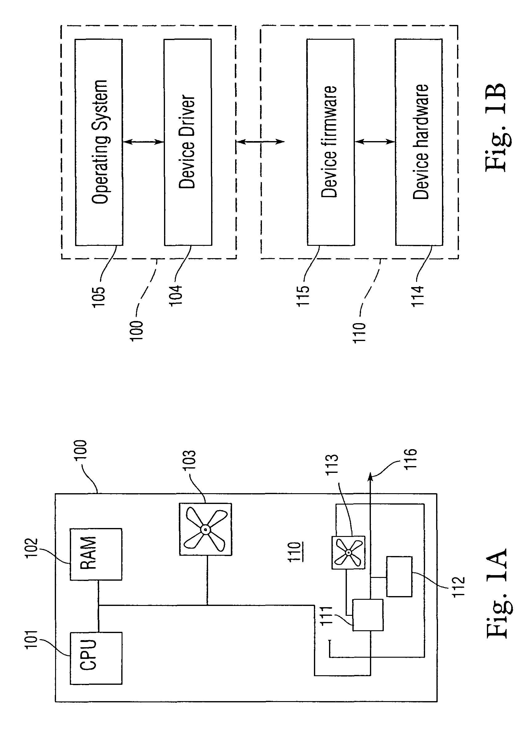
[0016]Although embodiments of the present invention are described herein in terms of host bus adapters (HBAs), it should be understood that the present invention is not limited to host bus adapters, but is generally applicable to any internal devices that are part of a host computer.

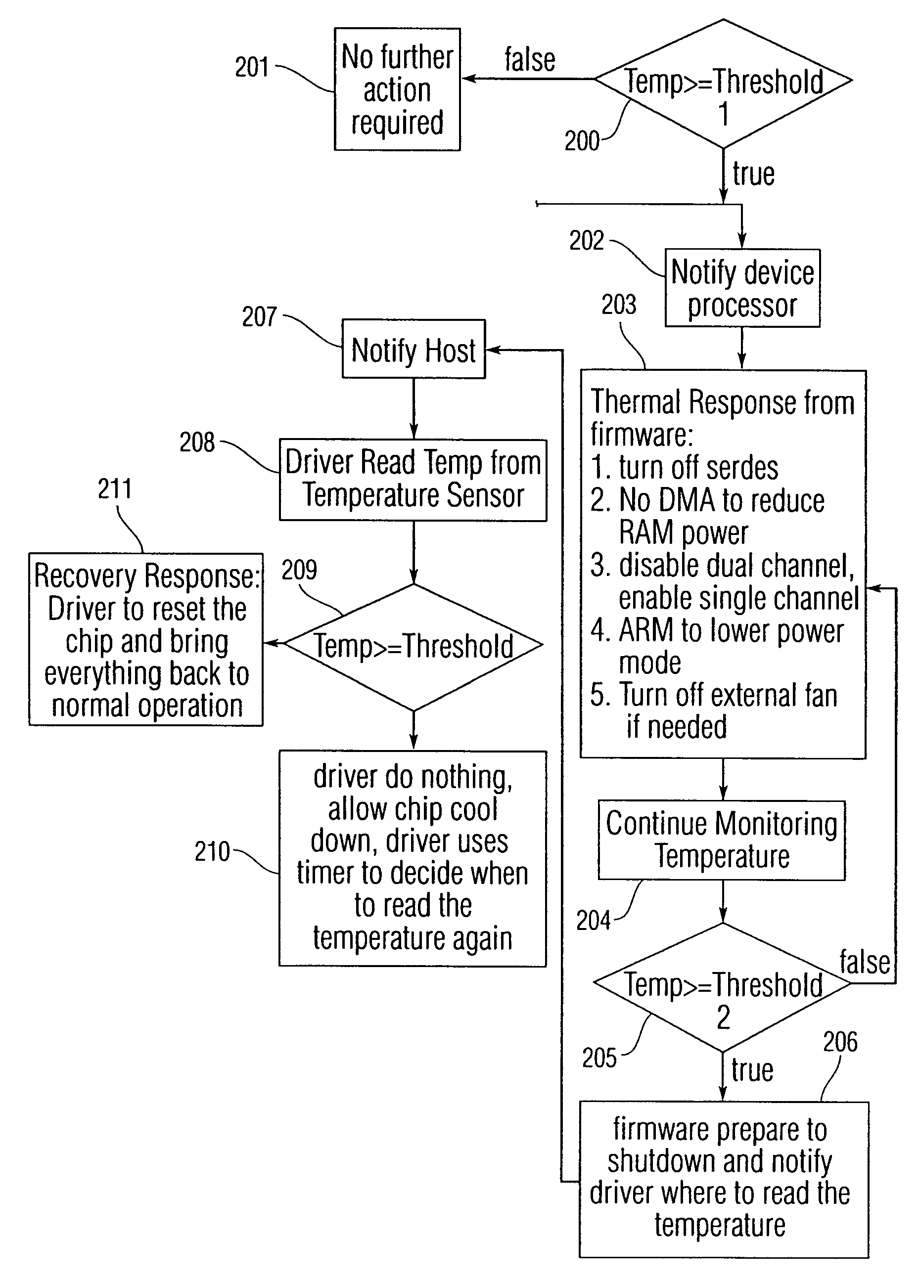
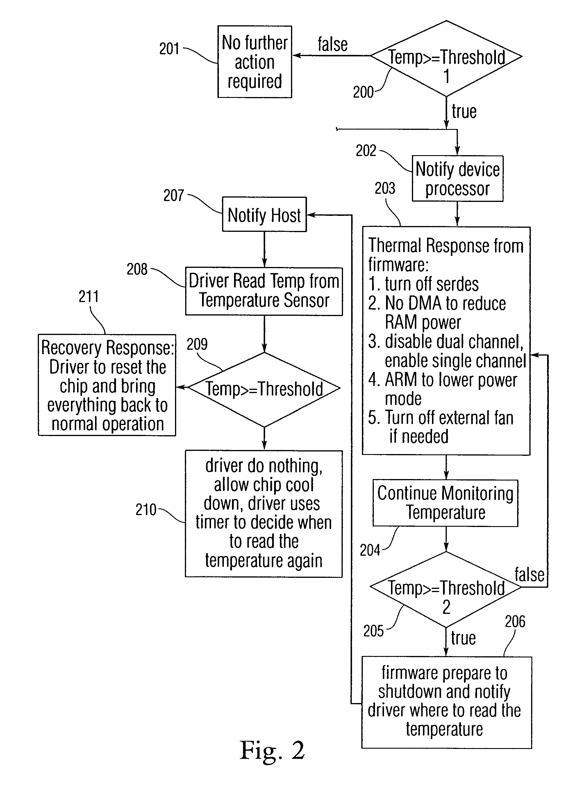
[0017]Embodiments of the present invention are directed to systems and methods for controlling the temperature of an internal device while reducing or minimizing the involvement of the host.

[0018]In particular, embodiments of the present invention provide for offloading as much of the...


PUM


Abstract

Embodiments of the present invention are directed to systems and methods for controlling the temperature of an internal device while reducing or minimizing the involvement of the host. Thus, some of the heat monitoring and remediation work may be offloaded to the actual device itself. The device may monitor its own temperature and, in the event of high temperature, perform device specific heat reduction actions without involving the host. Furthermore, the device may, upon detecting temperature within a predefined range, alert the host of a high temperature condition in order to allow the host to perform temperature reduction measures. Also, the device may, upon detecting temperature within a predefined range, alert the host of an impending device shutdown and shut the device down. In addition, the device may periodically save its temperature into non-volatile memory in order to create a temperature log.

Description

FIELD OF THE INVENTION[0001]This invention relates to protecting electronic devices from overheating, and more particularly to protecting a chip which is part of a general purpose host computer or server from over heating.BACKGROUND OF THE INVENTION[0002]Computers have various devices attached to them. These may include network cards, video cards, sounds cards, etc. These devices are considered part of a computer but many include some autonomous computational functionality as well. Thus, many of these devices include integrated circuits.[0003]Modern manufacturing technologies allow integrated circuits or chips to be manufactured with smaller and smaller feature sizes. For example, current technology may allow the manufacturing of chips with a 90 nm feature size. This allows more features to be placed on a chip of a given size, thus allowing an increase in functionality of a chip without increasing its size. However, placing more and more features in a small area increases the heat g...

Claims


Application Information

Patent Timeline
Patent Type & Authority Patents(United States)
IPC IPC(8): G06F15/00
CPCG06F1/206G05D23/1917
Inventor LIU, MICHAEL YUROACH, BRADLEY EUGENENGUYEN, VUONG CAOFIACCO, PETER MARKKWOK, SHAK LOONG
Owner AVAGO TECH INT SALES PTE LTD
Why Eureka
Try Eureka