Environmental control system for a vehicle

a technology for environmental control and vehicles, applied in the direction of refrigeration safety arrangement, process and machine control, refrigeration components, etc., can solve the problems of unrepresentative, unattractive, and unrepresentative, and achieve the effect of obscuring the driver's vision

Active Publication Date: 2011-05-24
MAGNA MIRRORS HLDG
View PDF82 Cites 71 Cited by
  • Summary
  • Abstract
  • Description
  • Claims
  • Application Information

AI Technical Summary

Benefits of technology

[0009]An advantage of the invention is that it provides design freedom to place the various sensor assemblies at positions most advantageous for a given situation, where the driver would not normally be aware of their presence. Hence they are not likely to distract the driver or obscure his vision. Further, by placing the second temperature and ambient humidity sensor assemblies away from the window temperature sensor assembly, which must necessarily be on or very close to the window, they are more likely to be representative of the ambient temperature or atmosphere in the main passenger cabin of the vehicle. Although in one application the outputs of the sensor assemblies are used in combination to predict internal window misting, their outputs can be used independently of each other, if desired, in order to measure the temperature and / or the humidity of the cabin, for the purposes of altering the environmental conditions of the cabin itself, in particular for the purposes of passenger comfort.
[0010]Preferably the window temperature sensor assembly is mounted for resilient biasing against the interior surface of the window.
[0011]In a preferred embodiment of the invention the system comprises a windscreen temperature sensor assembly for sensing the temperature of the interior surface of the windscreen, a humidity sensor assembly for sensing the ambient air humidity within the vehicle, and a second temperature sensor assembly for sensing the temperature of the humidity sensor assembly, wherein the windscreen temperature sensor assembly is mounted on an interior rearview mirror support bracket for engagement with the interior surface of the windscreen, and wherein the second temperature and humidity sensor assemblies are mounted within a rearview mirror housing mounted to the mirror support bracket.
[0012]In another aspect of the invention there is provided a temperature sensor assembly comprising a thermally insulating body, a temperature sensing element thermally insulated within the body, and a thermally conductive contacting element exposed externally of the body and in thermal communication with the temperature sensing element.
[0013]In yet another aspect of the invention there is provided a temperature sensor assembly comprising a thermally conductive element having a substantially planar exposed upper surface, a temperature sensing element in thermal communication with a lower surface of the thermally conductive element, a plurality of leads for the temperature sensing element extending downwardly away from said lower surface, and a generally tubular thermally insulating housing assembly having an upper end surrounding and supporting the temperature sensing element, the tubular housing assembly extending downwardly away from said lower surface of the thermally conductive element and having an internal air gap surrounding said leads.
[0014]In a still further aspect of the invention there is provided a mirror mounting system comprising a mounting bracket adapted for releasable connection to a vehicle window, and a sensor resiliently mounted to the bracket at a position such that, when the bracket is connected to the vehicle window, the sensor is urged against the window.

Problems solved by technology

A disadvantage of this unit is that its presence on the windscreen can be distracting to the driver and / or obscure his vision.
Also, by placing the ambient air temperature and ambient humidity sensor assemblies in the same housing as the windscreen temperature sensor assembly they are necessarily enclosed near to the windscreen and hence may not be truly representative of the ambient temperature or atmosphere in the main passenger cabin of the vehicle.
The presence of the unit and its cabling may also be aesthetically unattractive.

Method used


Image

  • Environmental control system for a vehicle
  • Environmental control system for a vehicle
  • Environmental control system for a vehicle

Examples


Embodiment Construction

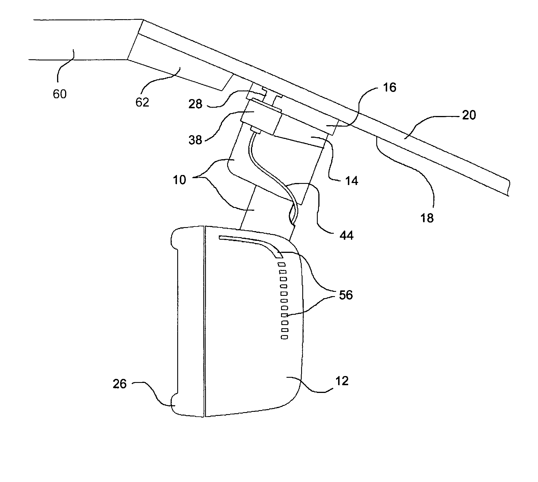
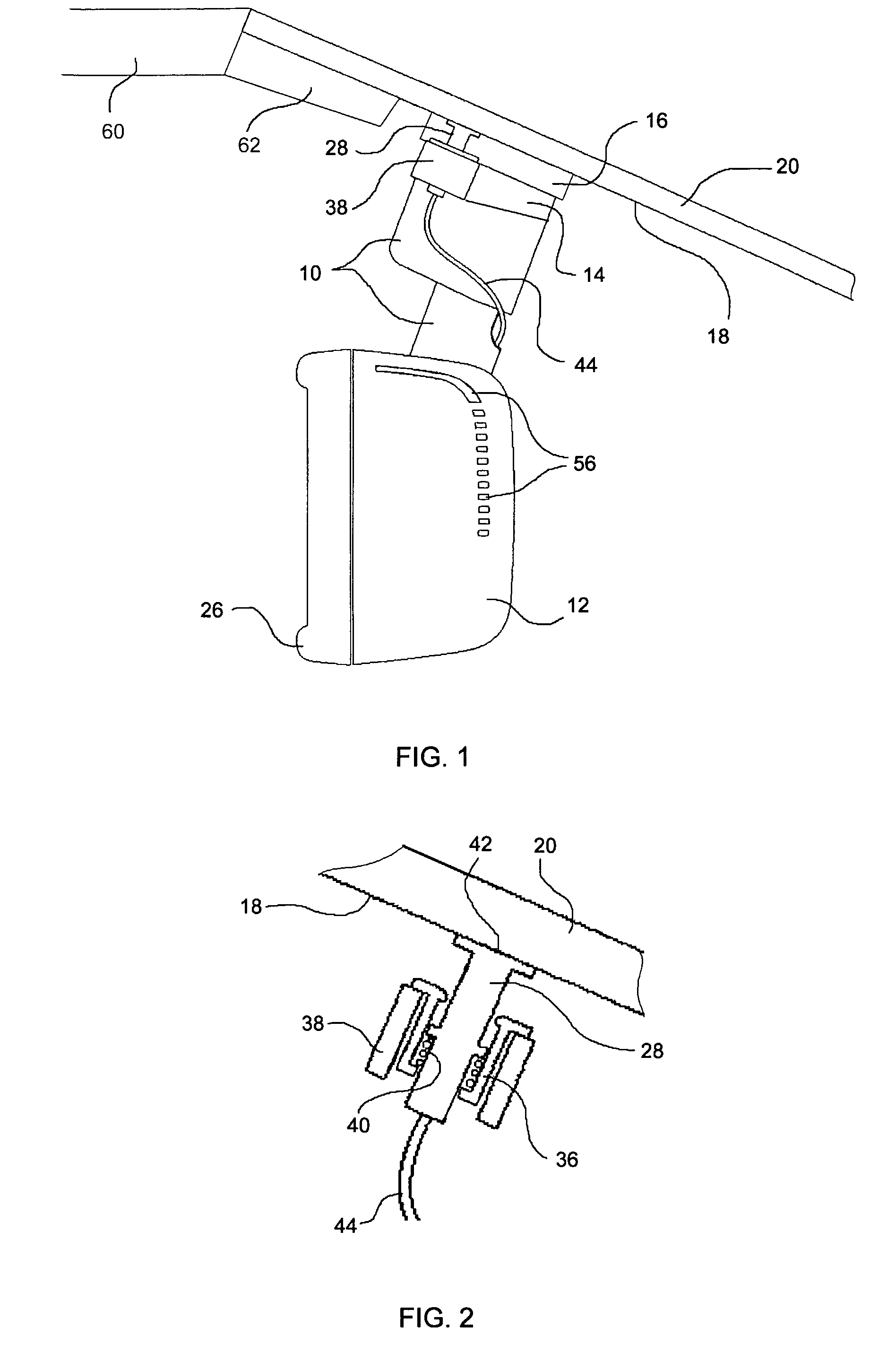
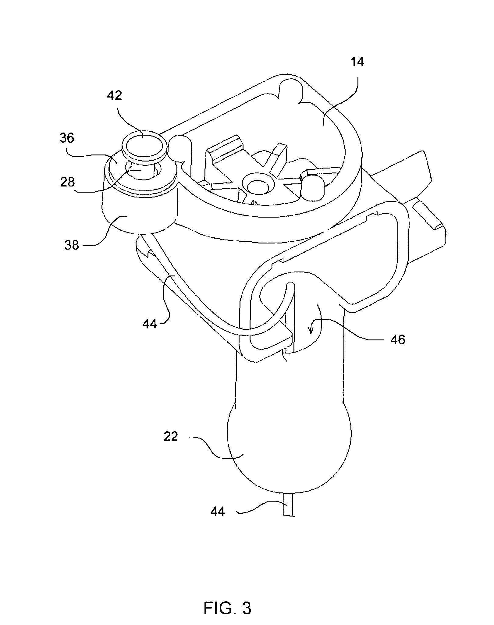
[0025]Referring now to the drawings, there is illustrated a vehicle environmental control system which comprises a mirror assembly comprising a mirror support bracket 10 and a rearview mirror housing 12. The bracket 10 has an upper end 14 for releasable attachment to a windscreen mounting member 16 which is adhesively secured to the interior surface18 of the vehicle windscreen 20. The mounting member 16 may take the form of a windscreen button, rails, or any other suitable attachment element. The lower end of the bracket 10 is in the form of a ball 22, FIG. 3, which engages a complementary socket (not shown) within the mirror housing 12 to allow universal rotational adjustment of the mirror. The mirror housing 12 has a front opening 24 which is normally closed by a reflective element (also not shown) held in place by a bezel 26. The reflective element may comprise an electro-optic cell so that the reflectivity of the mirror can be varied according to prevailing conditions. The brack...


PUM

PropertyMeasurementUnit
temperatureaaaaaaaaaa
humidityaaaaaaaaaa
resilient biasingaaaaaaaaaa

Abstract

An environmental control system for a vehicle, in particular for predicting internal misting of a vehicle windscreen, the system comprising a windscreen temperature sensor assembly 28, an ambient humidity sensor assembly 32 and a second temperature sensor assembly 30 for sensing the temperature of the humidity sensor assembly 32. The windscreen temperature sensor assembly 28 is mounted on an interior rearview mirror support bracket 10 for engagement with the interior surface 18 of the windscreen, and the second temperature and humidity sensor assemblies are mounted within a rearview mirror housing 12 mounted to the mirror support bracket 10.

Description

[0001]The present application is a 371 U.S. national phase application of PCT Application No. PCT / EP2005 / 010071, filed Sep. 15, 2005, which claims priority on Irish patent application No. S2004 / 0614, filed Sep. 15, 2004, and Irish patent application No. S2004 / 0838, filed Dec. 14, 2004.BACKGROUND OF THE INVENTION[0002]1. Field of the Invention[0003]This invention relates to an environmental control system for a vehicle, and in a preferred aspect to a system for predicting internal misting (fogging) of a vehicle window, especially but not limited to a vehicle windscreen.[0004]2. Prior Art[0005]U.S. Pat. No. 6,422,062 describes an integral sensor unit for predicting misting of a vehicle windscreen. The unit comprises a windscreen temperature sensor assembly, an ambient second temperature sensor assembly and an ambient air humidity sensor assembly, all contained within a common dome-shaped housing. In use the housing is attached to the interior surface of the windscreen and is connected...

Claims


Application Information

Patent Timeline
Patent Type & Authority Patents(United States)
IPC IPC(8): F24F3/14F25B49/00B60H1/00G01K3/00G01N25/02
CPCB60H1/00785B60H1/00792B60S1/0822G01N25/66B60S1/0866G01K7/22B60S1/0862G01K1/16
Inventor LYNAM, NIALL R.LAWLOR, PATRICK J.COADY, GARRETT
Owner MAGNA MIRRORS HLDG
Why Eureka
Try Eureka