Systems and methods for using ferrite alignment keys in wireless remote sensors

a technology of wireless resonant sensors and ferrite alignment keys, which is applied in the direction of instruments, fluid pressure measurement, mechanical actuation of burglar alarms, etc., can solve the problem of increasing the size of the sensor

Active Publication Date: 2011-05-24
WESTINGHOUSE AIR BRAKE TECH CORP
View PDF15 Cites 15 Cited by
  • Summary
  • Abstract
  • Description
  • Claims
  • Application Information

AI Technical Summary

Problems solved by technology

This leads to increase size of the sensor.

Method used


Image

  • Systems and methods for using ferrite alignment keys in wireless remote sensors
  • Systems and methods for using ferrite alignment keys in wireless remote sensors
  • Systems and methods for using ferrite alignment keys in wireless remote sensors

Examples


example 1

Affect of Ferrite Alignment Key Length on RFID Sensor Signal Intensity

[0045]A RFID tag from Sokymat USA (Cynthiana, Ky.) with an open center (about 5 mm opening) was used in combination with several ferrite alignment keys of different lengths (all 3-mm diameter ferrite rods).

[0046]FIG. 5A represents recorded measurement using ferrite alignment keys of different lengths upon inserted into both the RFID sensor and pick-up coil. The distance between the RFID sensor and pick-up coil was approximately 1 mm. The distance between the surface of the pick-up coil (opposite to the RFID sensor) and the edge of the ferrite alignment key was kept constant relatively negligible, D˜0 mm. FIG. 5B shows sensor signal intensity upon testing of ferrite alignment keys of different lengths. FIG. 5C presents the summary of testing results that illustrate that the sensor signal intensity increases as a function of the length of the ferrite alignment key. Because the distance between the surface of the pic...

example 2

Pressure Sensing Assembly with a Ferrite Alignment Key

[0047]A RFID tag from TagSys USA, Inc., Doylestown, Pa. (about 9 mm in diameter) was used in combination with a ferrite insert rod 3-mm in diameter, 5 mm long. The RFID tag was converted into a pressure sensor by attaching a pressure sensitive film to a surface of RFID sensor. The other side of the flexible membrane was metalized. The applied pressure flexed the membrane and the amount of electromagnetic field quenching was related to the applied pressure. FIG. 6A illustrates a control experiment layout of the measurement assembly without a ferrite insert. The applied pressure onto the RFID sensor produced a reproducible signal change. The maximum signal change was 15 ohm with applied pressure of 15 PSI (FIG. 6B). The calibration curve of the pressure response is presented in FIG. 6C.

[0048]FIG. 7A illustrates an experiment layout of the measurement assembly with a ferrite insert. The applied pressure onto the RFID sensor produced...


PUM


Abstract

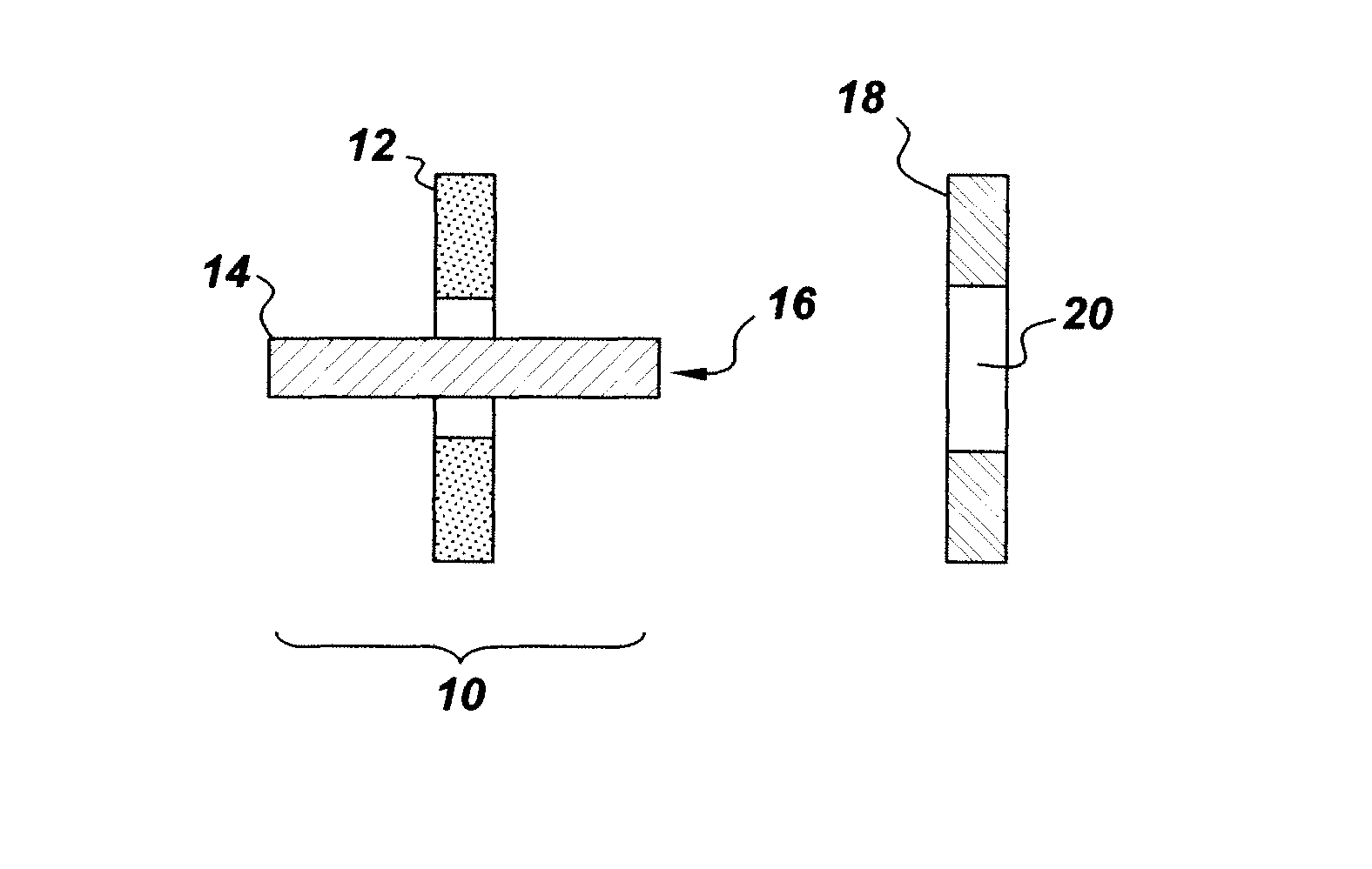
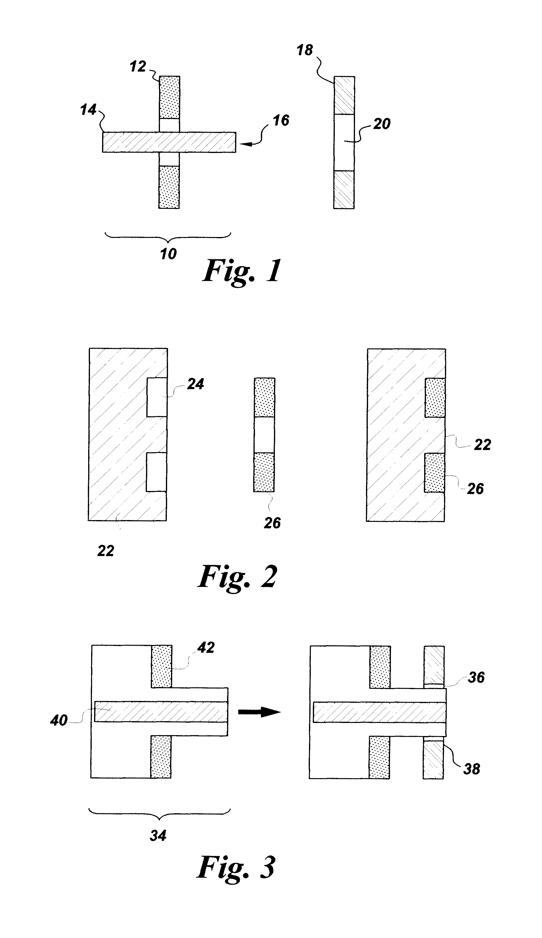
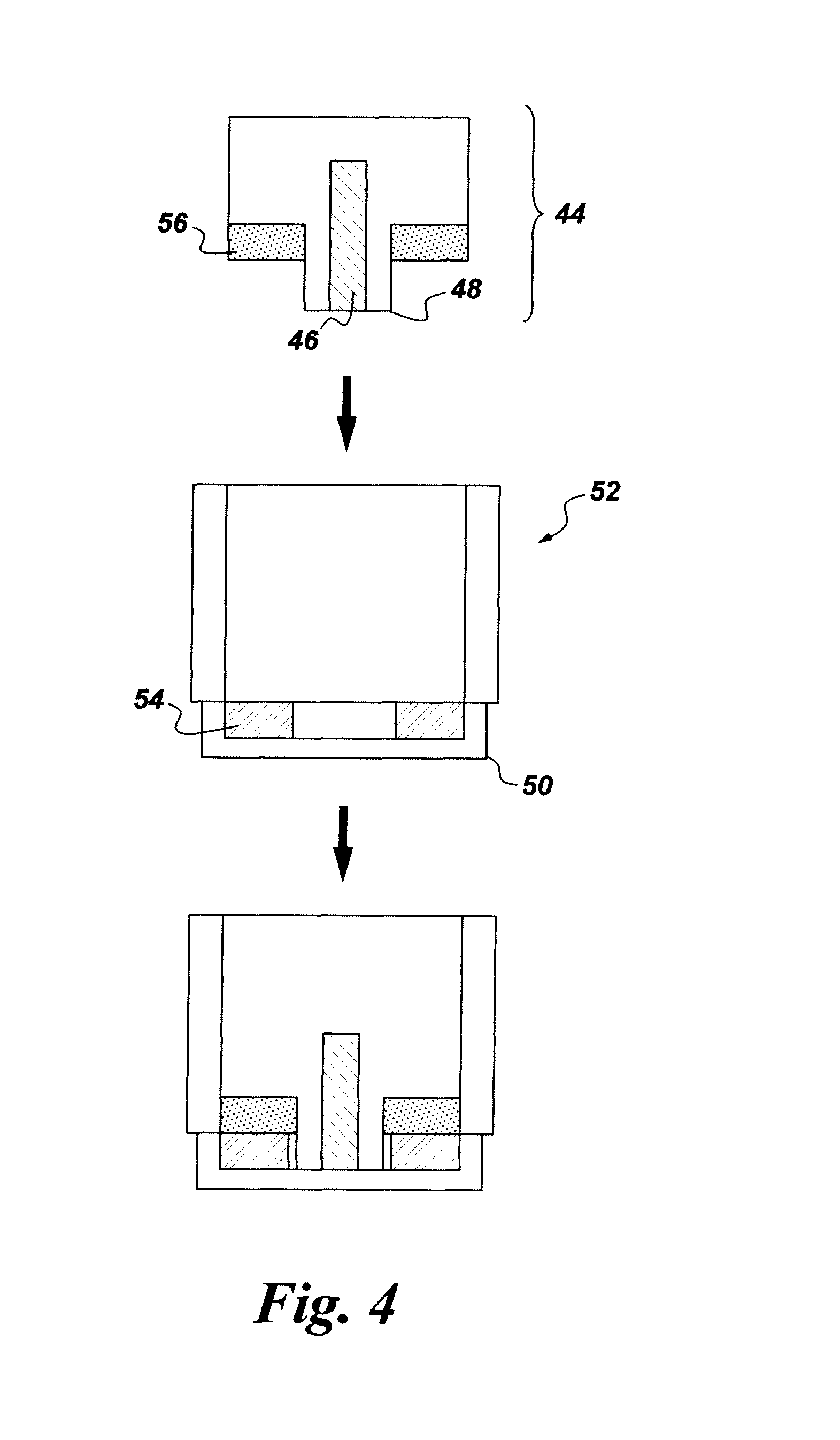
The present invention related to devices and methods for using ferrite alignment keys in wireless remote sensor assemblies. In one aspect, the invention provides wireless resonant sensor assemblies comprising a pick-up coil, a ferrite alignment key positioned in and extending from the pick-up coil, and wireless resonant sensor having a receiving element wherein the pick-up coil and the wireless resonant sensor align upon insertion of the ferrite alignment key into the receiving element. The ferrite alignment key may also be part of a resonant sensor such that insertion of a pick-up coil into a receiving element of the alignment key results in a configuration where the alignment key is positioned in and extended from the pick-up coil. Methods of measuring one or more parameters of a monitoring system are also provided. The insertion of the ferrite alignment key aligns the pick-up coil and wireless resonant sensor thereby increasing sensing of the wireless resonant sensor by the pick-up coil.

Description

BACKGROUND[0001]The invention relates generally to systems and methods for using ferrite alignment keys with wireless resonant sensors.[0002]A wireless resonant sensor functions by having a measurable resonance characteristic that varies in correspondence to changes in the environmental condition present at the sensor. When an excitation signal impinges on the sensor, the sensor emits a return signal representative of a state of the resonance characteristic. Measurable resonance characteristics include, electromagnetic resonance frequency, radio frequency, quality factor or bandwidth. In a passive wireless resonant sensor, the excitation signal is generated by a generator located separate and away from the sensor, and the excitation signal is then directed at the remote sensor. In semi-passive and active wireless resonant sensors the sensors rely on the use of onboard power for their operation. In passive, semi-passive, and active wireless sensors, the emitted return signal is detec...

Claims


Application Information

Patent Timeline
Patent Type & Authority Patents(United States)
IPC IPC(8): G08B13/14
CPCG01L19/083G01L9/007G06K7/10316G06K19/0716G06K19/0723
Inventor POTYRAILO, RADISLAV ALEXANDROVICHMORRIS, WILLIAM GUYDUMOULIN, CHARLES LUCIANSURMAN, CHERYL MARGARET
Owner WESTINGHOUSE AIR BRAKE TECH CORP
Why Eureka
Try Eureka