Image blur correcting unit, image blur correcting device, image pickup apparatus and portable equipment

a technology of image blur and correcting device, which is applied in the field of image blur correcting device, image pickup apparatus and portable equipment, can solve the problems of reducing affecting the accuracy of the correction mechanism, and inevitably increasing the size of the camera shake correction mechanism, etc., so as to achieve the effect of increasing the space for incorporating other electronic parts

Inactive Publication Date: 2011-05-31
FUJI PHOTO OPTICAL CO LTD
View PDF13 Cites 9 Cited by
  • Summary
  • Abstract
  • Description
  • Claims
  • Application Information

AI Technical Summary

Benefits of technology

[0008]Also, the present applicant has proposed and applied a drive structure in which not only an axis point, which is a point existing along the outer periphery of a holding module, is swingably supported but also the holding module is driven through first and second driving points respectively existing along the outer periphery of the holding module and spaced from the axis point in mutually different first and second directions, in the Japanese patent applications 2006-269712, 2006-269713, 2006-269714, 2006-269715 and the like as unpublished patent applications. Further, the present applicant has improved these applications to propose a technology aiming at enhancing the position detecting accuracy of the holding module when the holding module is swinging, as an image blur correcting unit disclosed in the Japanese patent application 2007-035341. When the drive structure proposed in these applications is realized, the size reduction of the image blur correcting unit can be realized, so that the image blur correcting unit can be incorporated into portable equipment.
[0078]According to this structure, the image blur correcting unit can be stored efficiently in a small space, namely, in the corner portions of the casing and thus the image blur correcting unit can be stored highly densely in the inside of the casing of the portable equipment. As a result of this, the image blur correcting unit does not occupy a large storage space in the inside of the casing, which can provide an effect that a space for incorporating other electronic parts can be increased.

Problems solved by technology

Therefore, a camera shake correcting mechanism inevitably tends to be increased in size.
When the size of the mechanism is tried to be reduced, there arises an inconvenience that bearing portions for the rotary joints, and the like are weakened.

Method used


Image

  • Image blur correcting unit, image blur correcting device, image pickup apparatus and portable equipment
  • Image blur correcting unit, image blur correcting device, image pickup apparatus and portable equipment
  • Image blur correcting unit, image blur correcting device, image pickup apparatus and portable equipment

Examples


second embodiment

[0169]Now, FIGS. 10˜14 are respectively explanatory views of a second embodiment according to the invention.

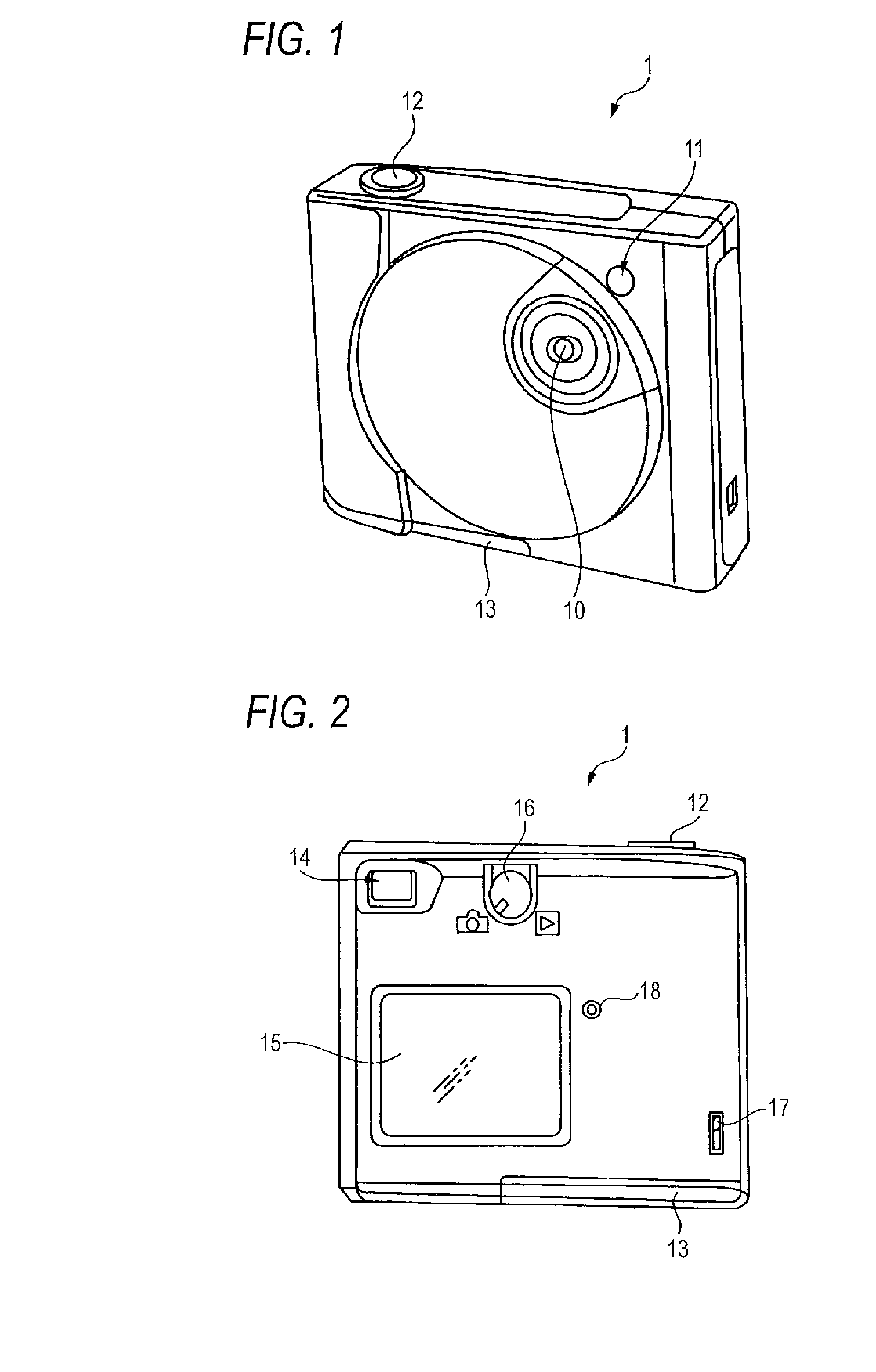
[0170]FIGS. 10A and 10B are external perspective views of a cellular phone which is an embodiment of portable equipment according to the invention.

[0171]FIG. 10A shows the front view of a cellular phone 400. The cellular phone 400 includes on the front surface thereof: a liquid crystal panel 401 on which a menu screen, a picked-up image or the like can be displayed; an ear piece 402 which incorporates a speaker (see FIG. 11) therein and is used to send out a sound emitted from the speaker into space; a select button 404 which can be used as a shutter button when selecting various functions or picking up an image; a push button 405 for inputting telephone number; a mouthpiece 406 which incorporates a microphone (see FIG. 11) therein and is used to transmit a voice to the microphone; a determination button 407 for determining telephone number or the like input by a user; a power...

first embodiment

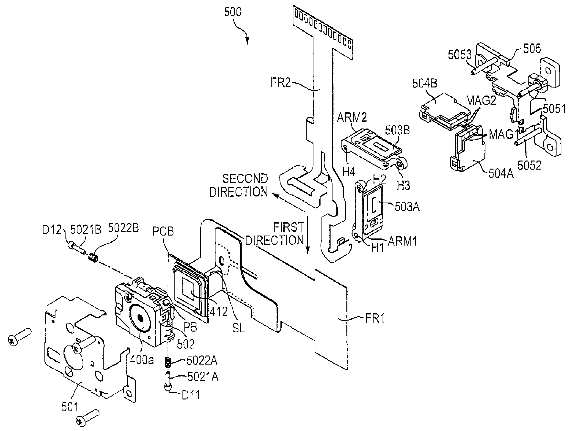
[0199]Also, in this example, similarly to the first embodiment, there is shown a structure in which not only the lens but also the CCD 412 are held by the holding module 502; and, therefore, to the holding module 502 which can be swung, there is connected the flexible board FR1 for image signal transfer. Referring to the connection of the flexible board FR1 specifically, one end of the flexible board FR1 is connected to the sensor board PCB on which the CCD 412 is mounted; and, the portion of the flexible board FR1 that extends at least first from the sensor board PCB is connected in such a manner that it extends outwardly from the holding module 402 in a direction oblique both to a first direction connecting an axis point PB and first driving point D11 and to a second direction connecting the axis point PB and second driving point D12. Further, as shown in FIG. 12, in the portion of the flexible board FR1 that extends at least first from the sensor board PCB in the above oblique di...

third embodiment

[0230] the portion of the flexible board FR1 extending outwardly first from the holding module 502 is divided to a first portion FR11 extending outwardly through between the axis point PB and first driving point D11 and a second portion FR12 extending outwardly through between the axis point PB and second driving point D11; and, the first and second portions FR11 and FR12 are pulled out separately and then they join together outside the holding module 502 to thereby constitute a single flexible board FR1. In this case as well, there can be provided the same effect.

[0231]As has been described heretofore, the invention can realize an image blur correcting unit structured such that a flexible board itself is difficult to deform and the flexible board is difficult to remove from its connecting portion, an image blur correcting device incorporating the image blur correcting unit therein, an image pickup apparatus incorporating the image blur correcting device therein, and compact portabl...


PUM


Abstract

In the image blur correcting unit, one end of a flexible board is connected to a sensor board included in a holding module, and the portion of the flexible board that extends at least first from the sensor board extends outwardly from the holding module in a direction oblique to both first and second directions. That is, the flexible board is extended from the vicinity of an axis point which swings least while the holding module is swinging.

Description

BACKGROUND OF THE INVENTION[0001]1. Field of the Invention[0002]The present invention relates to: an image blur correcting unit which is suitably used as a camera shake correcting mechanism for an image pickup apparatus such as a digital camera, a camera-equipped portable telephone; an image blur correcting device comprising the image blur correcting unit; an image pickup apparatus comprising the image blur correcting device; and a portable equipment having the image pickup apparatus.[0003]2. Description of the Related Art[0004]In the related art, in digital cameras and the like, various camera shake correcting mechanisms are employed in order to suppress a disturbance of a photographed image due to a camera shake of the user, or the like (see JP-A-7-274056, JP-A-2005-326807 and Japanese Patent No. 2,612,371).[0005]As such camera shake correcting mechanism, in the related art, there is a so called gimbal mechanism in which a holding module for holding an imaging lens can be swung in...

Claims


Application Information

Patent Timeline
Patent Type & Authority Patents(United States)
IPC IPC(8): H04N5/228
CPCG03B5/08H04N5/2253H04N5/23248G03B2205/0007G03B2205/0069G03B2217/005H04N23/54H04N23/68
Inventor SEKINO, SHIZUOYOSHIDA
Owner FUJI PHOTO OPTICAL CO LTD
Why Eureka
Try Eureka