Method, device and system for determining an indoor position

a technology for indoor positioning and methods, applied in surveying and navigation, navigation instruments, instruments, etc., can solve problems such as the limitation of space of moving objects, and achieve the effect of improving position detection accuracy

Inactive Publication Date: 2018-10-11
SIEMENS MOBILITY GMBH
View PDF0 Cites 8 Cited by
  • Summary
  • Abstract
  • Description
  • Claims
  • Application Information

AI Technical Summary

Benefits of technology

[0015]Thus, by combining data from two different methods, accuracy is enhanced.
[0021]In particular, at least one further location determination method providing further position data is used for deriving the position of the moving object. This further enhances position detection accuracy.

Problems solved by technology

Additionally, an indoor position denotes a position where there is no GPS or similar signal available; however, there are limitations of the space the moving object is in.

Method used


Image

  • Method, device and system for determining an indoor position
  • Method, device and system for determining an indoor position
  • Method, device and system for determining an indoor position

Examples


Embodiment Construction

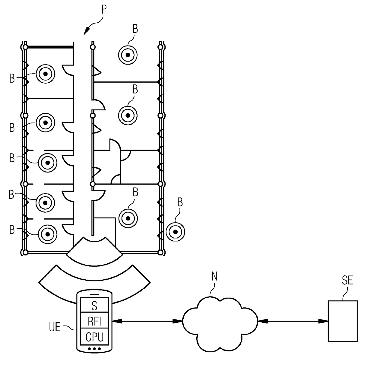
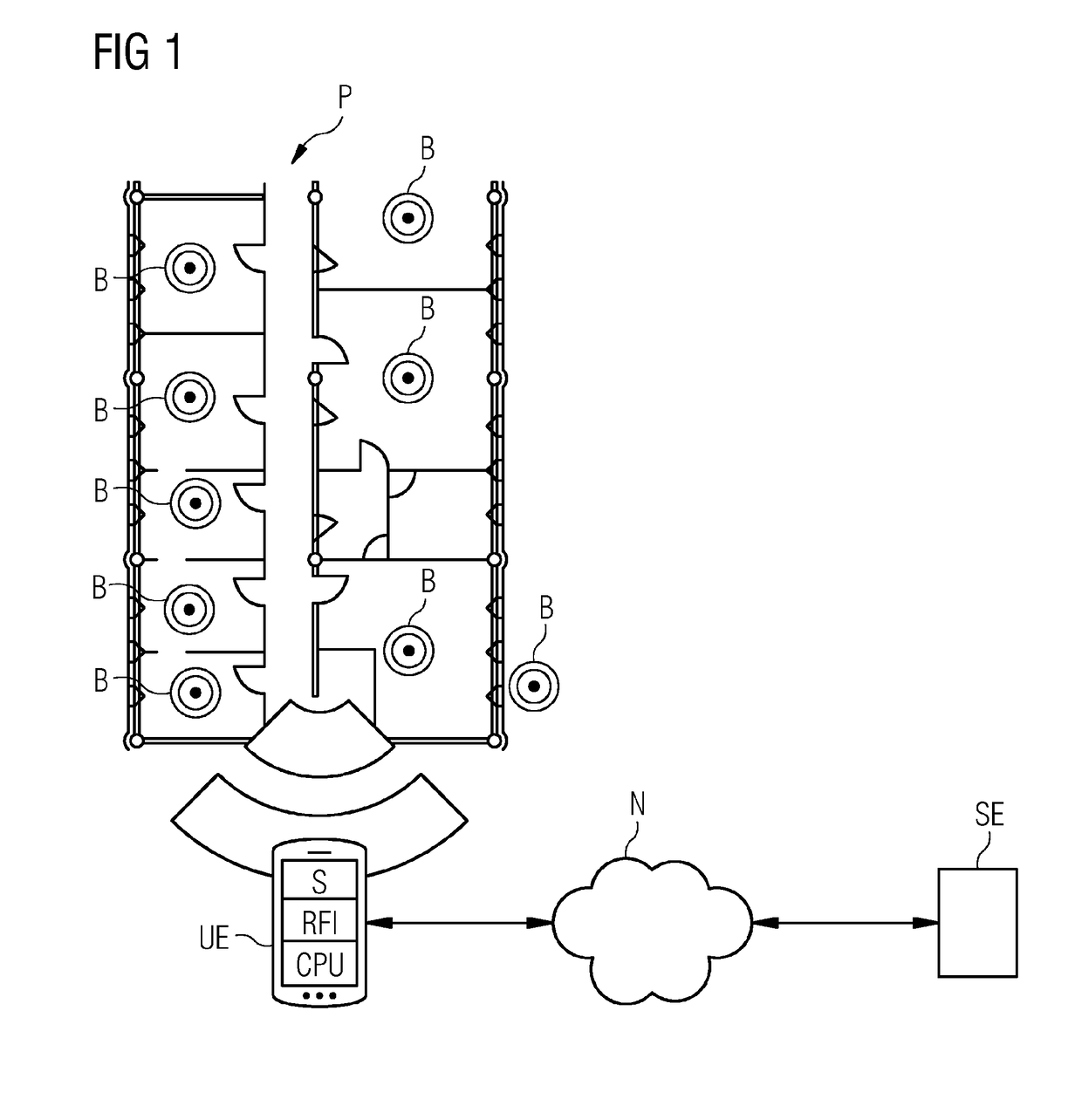
[0030]In the embodiment of a system architecture shown in FIG. 1, a number of Bluetooth Low Energy (BLE) beacons B are positioned in selected locations in an indoor environment, (e.g., inside of rooms), as shown on the floor plan.

[0031]The beacons B may be located at central positions, such as the position where the lamp is mounted. Alternatively, or additionally, the beacons B are mounted at position where the necessary infrastructure such as power supply is already available.

[0032]Both the beacon locations and respective unique identifiers such as Medium Access Control (MAC) addresses are stored. The locations and unique identifiers may be stored in a database and related to each other, e.g. in view of position, distance, etc. The precise whereabouts of the beacons B, as well as the layout of the respective floor or floor plan of the location, (e.g., of the premises P depicted in FIG. 1), are known. If they are known, no calibration for the first position detection method is requi...


PUM


Abstract

The disclosure relates to a method for determining an indoor position of a moving object. The method includes using a first location determination method for determining first position data; using at least a second location determination method for determining second position data; and deriving a position of the moving object by combining first and second position data gathered from both systems.

Description

[0001]The present patent document is a § 371 nationalization of PCT Application Serial Number PCT / EP2016 / 069461, filed Aug. 17, 2016, designating the United States, which is hereby incorporated by reference, and this patent document also claims the benefit of DE 10 2015 219 836.7, filed Oct. 13, 2015, which is also hereby incorporated by reference.TECHNICAL FIELD[0002]The disclosure relates to a method, a device, and a system or determining an indoor position of a moving object.BACKGROUND[0003]Indoor positioning offers the possibility of locating users in an indoor environment, e.g., inside buildings. Thus, e.g., targeted advertising, navigation, rescue services, healthcare monitoring, etc. are facilitated.[0004]Different approaches are known, amongst them radio frequency (RF) based techniques such as the following techniques.[0005]In one technique, received signal strength indicator (RSSI)—non distance based calculations, which are also referred to as “fingerprinting”, are used. Th...

Claims


Application Information

Patent Timeline
Patent Type & Authority Applications(United States)
IPC IPC(8): G01C21/20G01S5/02G01S19/49
CPCG01C21/206G01S5/0263G01S5/0294G01S19/49
Inventor JIMENEZ GONZALEZ, MOISES ENRIQUERAMIREZ, ALEJANDROSCHINDHELM, CORINA KIM
Owner SIEMENS MOBILITY GMBH
Why Eureka
Try Eureka