
Touch Sensing Systems

a technology of touch sensing and sensing devices, applied in the direction of instruments, electric digital data processing, input/output process of data processing, etc., can solve the problems of lumio is more sensitive and add product cost, and achieve the effect of low cost, minimal additional cost and improved accuracy

Inactive Publication Date: 2012-03-15
LIGHT BLUE OPTICS
View PDF2 Cites 9 Cited by
  • Summary
  • Abstract
  • Description
  • Claims
  • Application Information

AI Technical Summary

Benefits of technology

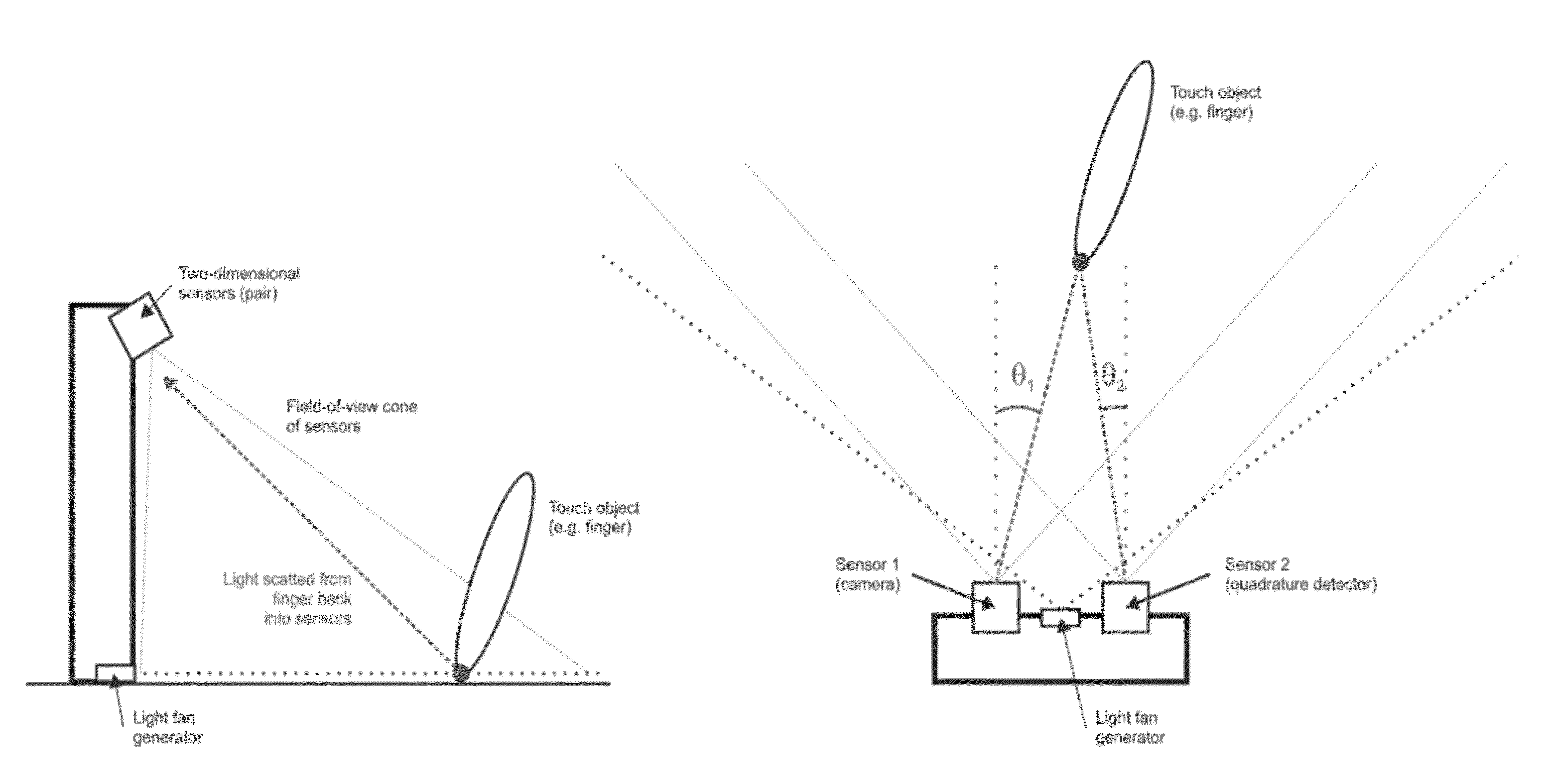
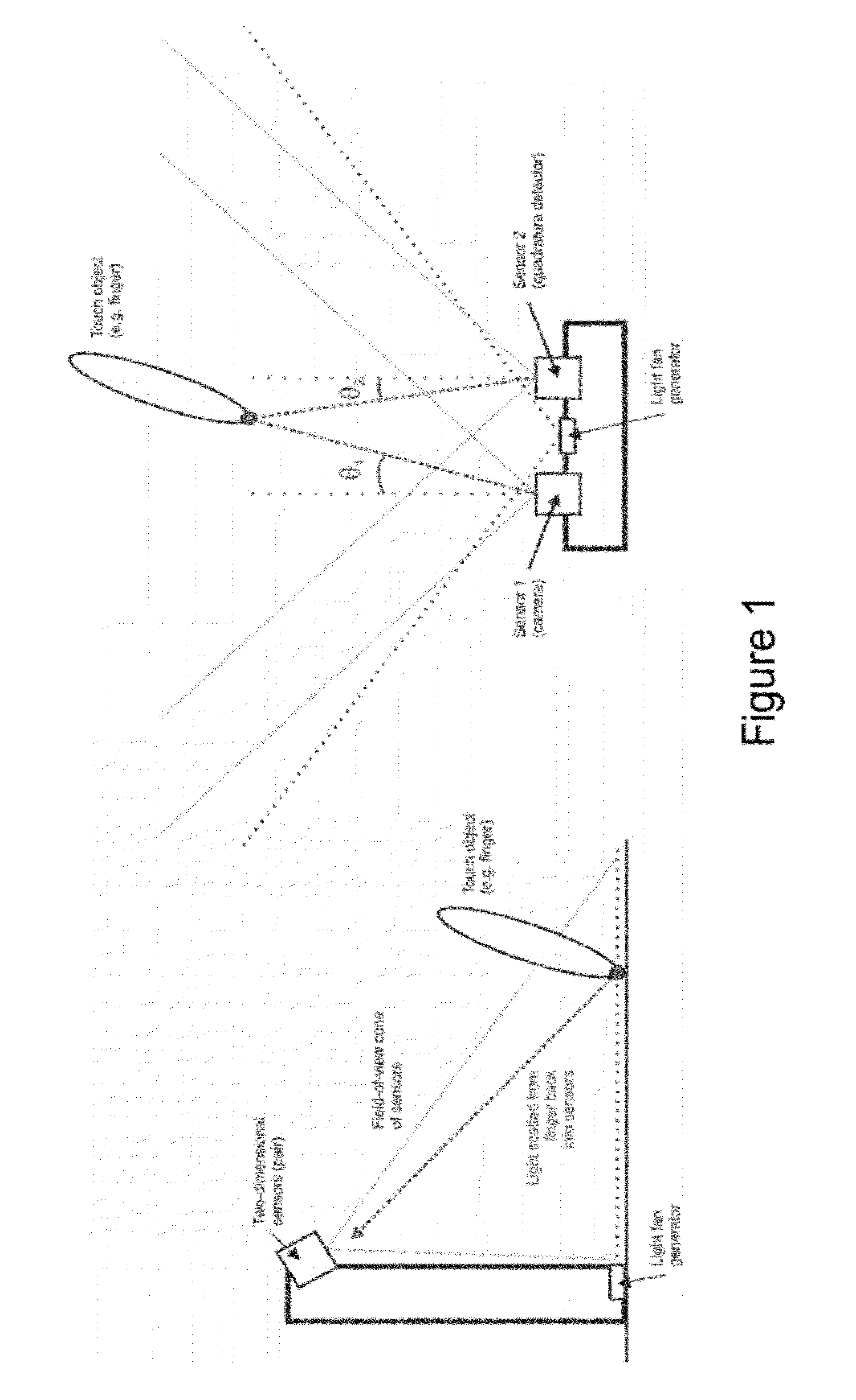
[0008]This invention is concerned with a two-sensor approach. In preferred embodiments one of the two-dimensional sensors is a conventional camera, and the second of the two-dimensional sensors is a very low cost quadrature detector (essentially an array of 2×2 photodiodes). Embodiments of the invention provide for the improved accuracy possible through a triangulation approach, at minimal additional cost to a single-sensor (camera) approach. Position detection accuracy using this approach is strictly improved relative to using just a single camera sensor (as per Lumio '368), even given a significantly higher level of error expected from position sensing using a quadrature detector, relative to a camera.

Problems solved by technology

Both arrangements have disadvantages in practice; the Montellese two-sensor approach potentially results in additional product cost compared to Lumio which utilizes only a single sensor, whereas Lumio is more sensitive to error in the detected position since triangulation cannot be employed.

Method used


Image

  • Touch Sensing Systems
  • Touch Sensing Systems
  • Touch Sensing Systems

Examples


Embodiment Construction

Touch Sensing Techniques

[0013]We describe a system for detecting touch events on or near a surface consisting of a “fan generator” which forms a fan of light (advantageously, but not limited to, invisible light such as infra-red light, so as not to result in visual disturbance to the user) above a surface. The fan of light may most advantageously be disposed parallel to the surface (to avoid intersection with, and hence scatter from, the surface), but in other embodiments may be disposed at an angle to the surface. A pair of sensors are disposed side-by-side at some distance above the surface, angled such that the field of view of the sensors captures the desired touch detection area, such that one or more objects (such as a finger) intersecting the fan of light will cause scatter, which is detected by a pair of sensors, configured (potentially with one or more lenses) such that the angle of light from the detected object to the sensor is converted to position of light detected on t...


PUM


Abstract

The invention relates to techniques for sensing of touch events near to a surface using position data from a pair of two-dimensional sensors (a camera and a quadrature detector). We describe apparatus for detecting the location of one or more objects on, or adjacent to, a surface, the apparatus comprising: an illuminator generating a generally planar fan of light above said surface; a pair of two-dimensional sensors, positioned above said surface comprising a camera, and a quadrature detector; and processing circuitry for receiving output from said sensors, and returning an estimate of said object location

Description

CROSS REFERENCE TO RELATED APPLICATION[0001]This application claims priority to U.S. Provisional Patent Application No. 61 / 381,098 entitled “Touch Sensing Systems” and filed Sep. 9, 2010. The entirety of the aforementioned applications is incorporated herein by reference for all purposes.BACKGROUND OF THE INVENTION[0002]This invention generally relates to techniques for sensing of touch events near to a surface using position data from a pair of two-dimensional sensors (a camera and a quadrature detector).[0003]Arrangements for detecting touch events on (or close to) a surface, onto which a template may be placed or images projected, are known in the prior art. In particular, Montellese (U.S. Pat. No. 6,281,878) discloses forming a fan of light (such as infra-red light from a laser) parallel to, and slightly above, a surface, with a pair of two-dimensional sensors angled acutely to the surface, which pick up reflected (scattered) light from an object (such as a finger) impinging on ...

Claims


Application Information

Patent Timeline
Patent Type & Authority Applications(United States)
IPC IPC(8): G06F3/042
CPCG06F3/0421
Inventor CABLE, ADRIAN J.
Owner LIGHT BLUE OPTICS
Learn More