
Towed array deployment system for unmanned surface vehicles

a technology for unmanned surface vehicles and deployment systems, which is applied in the direction of towing/pushing equipment, instruments, vessel construction, etc., can solve the problem that the towed array cannot be very easily pushed, and achieve the effect of facilitating the deployment of the towed array

Inactive Publication Date: 2011-06-07
THE UNITED STATES OF AMERICA AS REPRESENTED BY THE SECRETARY OF THE NAVY
View PDF5 Cites 5 Cited by
  • Summary
  • Abstract
  • Description
  • Claims
  • Application Information

AI Technical Summary

Benefits of technology

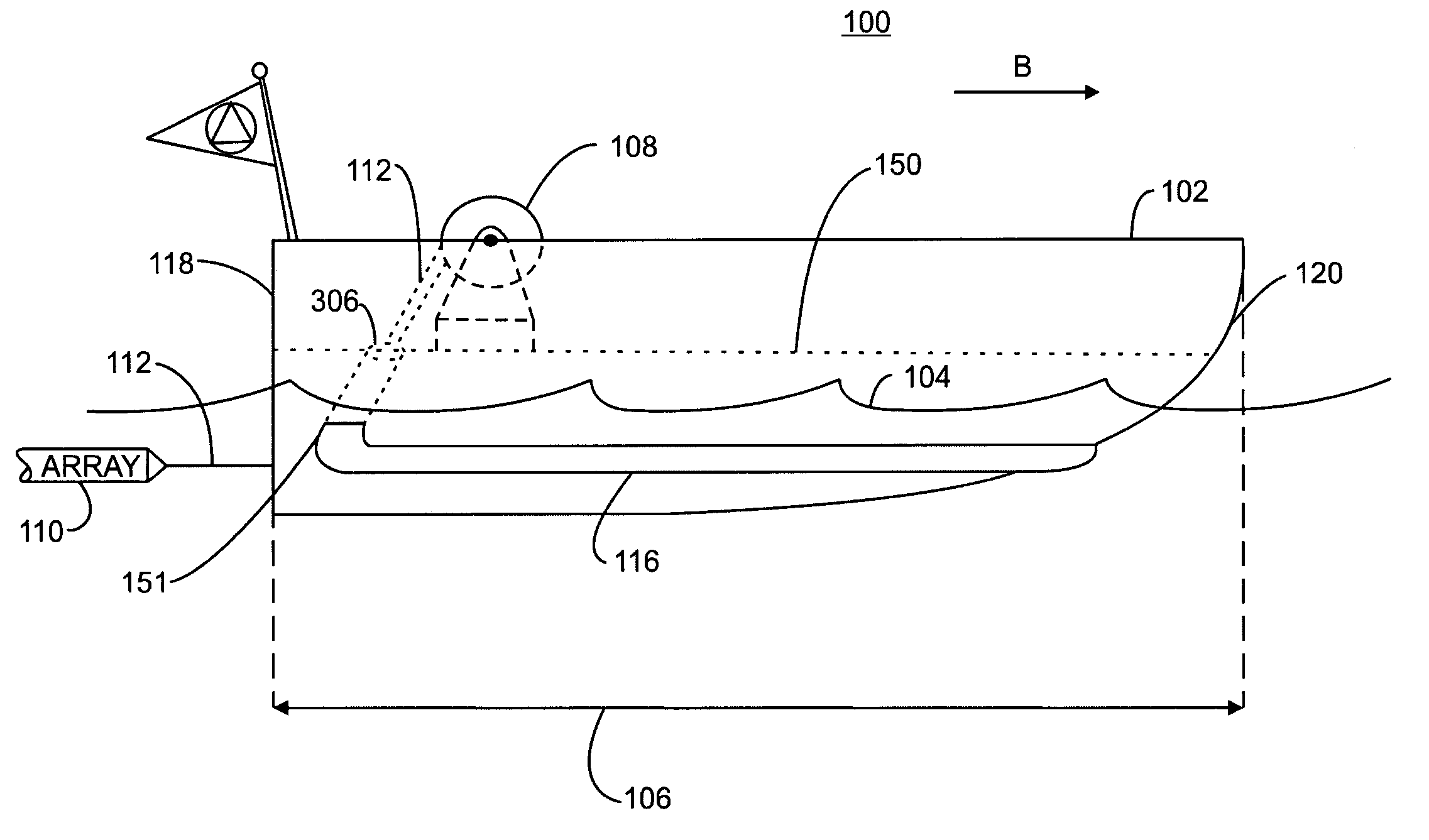
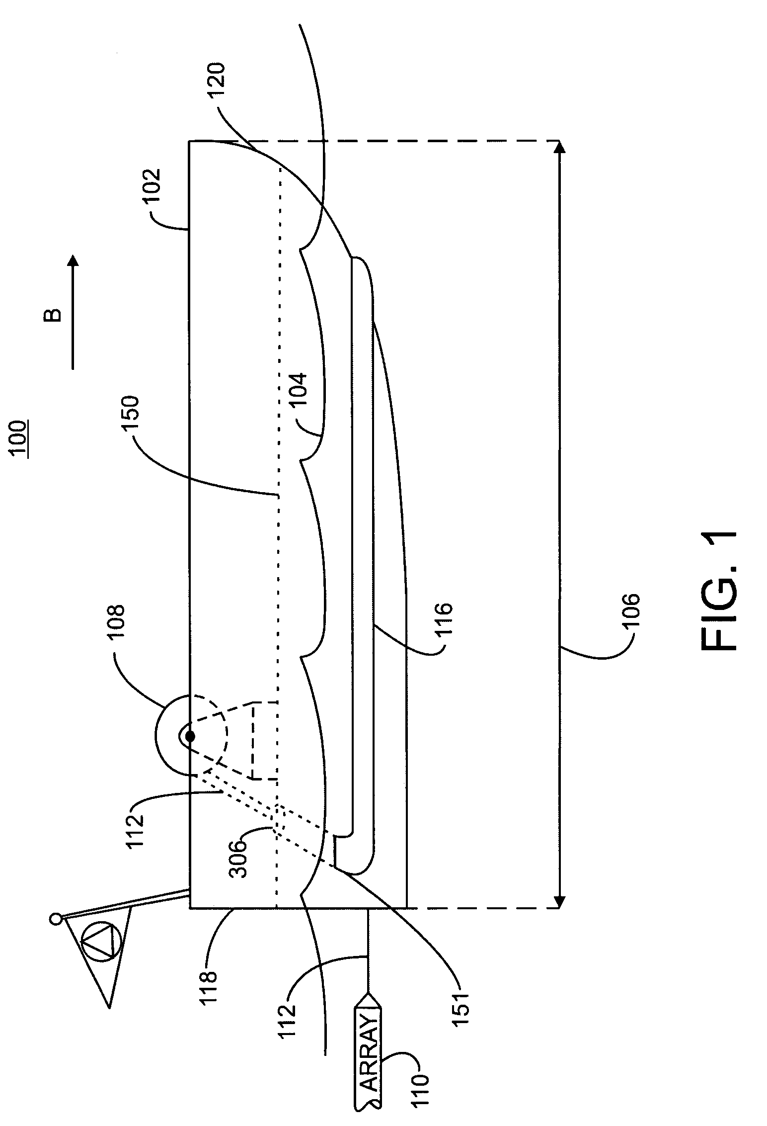
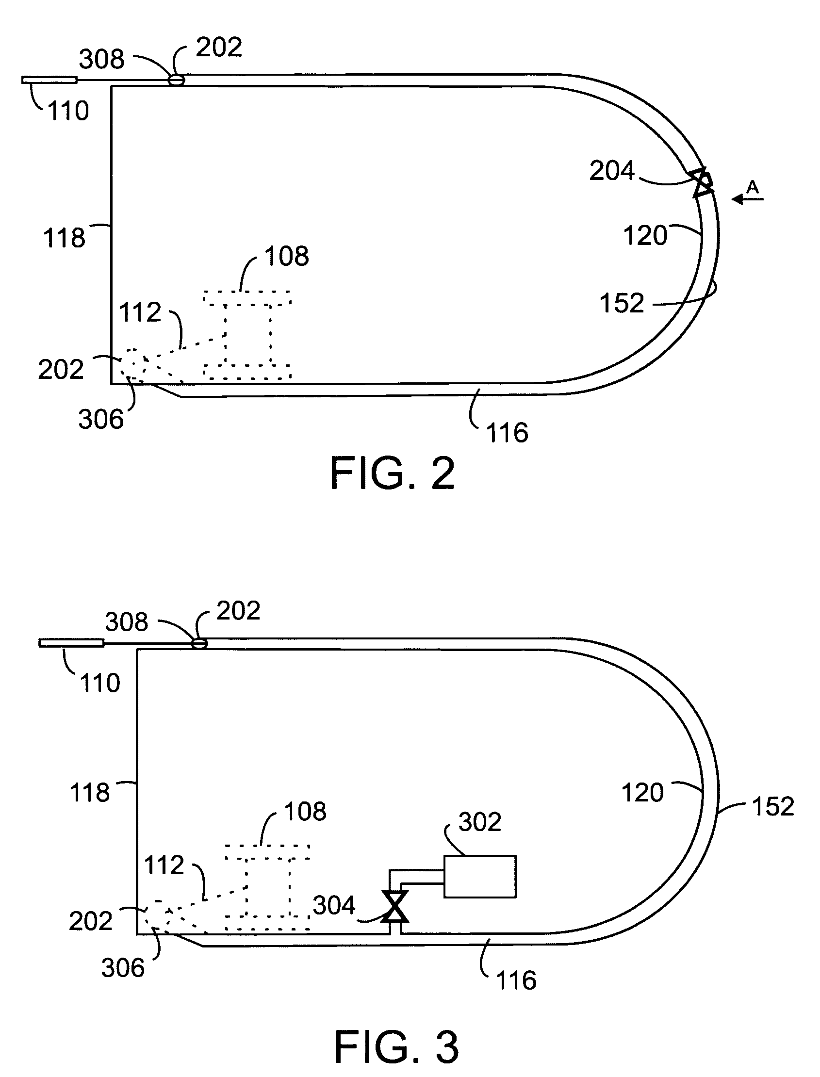
[0015]A winch is attached to the watercraft preferably on the deck of the watercraft. The winch is disposed adjacent a first one of the two open ends of the tube. A tow cable and towed array are stored on the winch and extend from the winch through the first open end and at least partially through the interior of the tube. This arrangement facilitates deployment of the towed array by the fluid introduced into the interior by the fluid injection system to deploy from the winch, along the interior of the tube and out a second one of the two open ends.

Problems solved by technology

Since the towed array is similar to a flexible rope that is constructed to be pulled, the towed array cannot be very easily pushed.

Method used


Image

  • Towed array deployment system for unmanned surface vehicles
  • Towed array deployment system for unmanned surface vehicles
  • Towed array deployment system for unmanned surface vehicles

Examples


Embodiment Construction

[0027]Referring initially to FIG. 1, an exemplary embodiment of a towed array deployment system 100 in accordance with the present invention is illustrated. The towed array deployment system includes a small surface watercraft 102 having a stern 118 and a bow 120. Suitable small surface watercraft include, but are not limited to Unmanned Surface Vehicles (USVs), manned vessels and semi-submersibles.

[0028]In general, the watercraft has an overall length 106 of less than 12 meters and preferably in the range of 7 meters to 11 meters. As used herein, the overall length of the watercraft, in feet or meters, is measured from the foremost part of the bow to the aftermost part of the stern, including any fixed projections extending beyond the bow and stern.

[0029]The watercraft 102, when either at rest or moving through the water includes a waterline 104 (representative of the fluid in which the watercraft floats). The towed array deployment system also includes an external tube 116 attache...


PUM


Abstract

A towed array deployment system is provided that uses the flow of fluid through the interior of a tube to deploy a towed line array. The system includes a small surface water craft such as an unmanned surface vehicle having a length between seven and eleven meters and a U-shaped tube mounted to the outside of the hull of the watercraft below the waterline. A towed array is fed from a winch aboard the surface craft, through one end of the tube, and the fluid is introduced through into the interior of the tube to force the towed array for deployment through the tube and out a second end of the tube near the stern of the watercraft.

Description

STATEMENT OF GOVERNMENT INTEREST[0001]The invention described herein may be manufactured and used by or for the Government of the United States of America for Governmental purposes without the payment of any royalties thereon or therefor.CROSS REFERENCE TO OTHER PATENT APPLICATIONS[0002]None.BACKGROUND OF INVENTION[0003]1) Field of the Invention[0004]The present invention is directed to a method and system for the deployment and retrieval of linear arrays off of Unmanned Surface Vehicles (USVs).[0005]2) Description of Prior Art[0006]Sonar systems are used to determine the direction of propagating underwater signals and hence the location of the source of these signals. Sonar systems utilize arrangements or arrays of sources and receivers to detect arriving signals and to determine the direction from which these signals originated. For example, appropriate time delays applied to the receivers serve to steer the array and to calculate the direction of arrival of the incoming signals.[...

Claims


Application Information

Patent Timeline
Patent Type & Authority Patents(United States)
IPC IPC(8): B63B21/16
CPCB63B21/66G01V1/3843B63B2035/006
Inventor STOTTLEMYER, THOMAS R.MEWER, RICHARD C.MAUGLE, MARK A.
Owner THE UNITED STATES OF AMERICA AS REPRESENTED BY THE SECRETARY OF THE NAVY
Learn More