Al technical title is built by PatSnap Al team. It summarizes the technical point description of the patent document.
a technology of mobility assistance and equipment, applied in the field of mobility assistance equipment, can solve the problems of user's body, excessive amount of energy needed to stabilize the walking system, and many of the same functional limitations of the modern ambulatory aid, and achieve the effects of improving the mobility of a person, high function, and low cos
Inactive Publication Date: 2011-06-07
BIOQUEST PROSTHETICS
View PDF66 Cites 24 Cited by
Summary
Abstract
Description
Claims
Application Information
AI Technical Summary
This helps you quickly interpret patents by identifying the three key elements:
Problems solved by technology
Method used
Benefits of technology
[0013]An object of the present invention is to address the aforementioned needs. To this end, the present invention is an improved, low cost, high function mobility assistance apparatus which improves the mobility of a person using the apparatus as a walking aid. The apparatus has improved loading response shock absorption and sagittal plane positive kinetic power which is needed for doing the work of walking. An embodiment of the mobility assistance apparatus of the invention comprises a support member capable of bearing vertical forces during use of the support member as a walking aid, and a device connected to a lower portion of the support member for ground engagement. The device includes a resilient foot, ankle and shank which store energy during force loading and release stored energy during force unloading to generate forward propulsive force to aid mobility with ambulation using the apparatus as a walking aid. The ankle and shank are formed by a resilient member having a reversely curved lower end secured to the foot to form the ankle and extending upward from the foot by way of an anterior facing convexly curved portion of the member. The resilient member is secured to the foot by way of a coupling element which houses the reversely curved lower end of the member. With this construction, the apparatus has improved spring efficiency for enhancing loading response shock absorption and sagittal plane positive kinetic power when the apparatus is used as a walking aid during ambulation. The resilient member, coupling element and foot in a preferred form of the invention are monolithically formed, as by extrusion, molding, casting and / or machining, which can lower the manufacturing cost.
[0015]According to another feature of the invention, the support capable of bearing vertical forces during use of the apparatus, is resilient and flexes to store additional energy during force loading and release stored energy during force unloading to aid mobility with ambulation using the apparatus as a walking aid. In a disclosed embodiment, the resilient support is anterior facing convexly curved over at least most of the height of the support, and forms a curvilinear thigh shank connected to an upper end of the shank of the device for ground engagement. A posterior shank device can be employed on at least one of the thigh shank of the support and the shank of the device to store additional energy on expansion of the at least one of the thigh shank and shank of the device under force loading and to release the stored energy during force unloading to aid mobility.
Problems solved by technology
As such, modern ambulatory aids continue to suffer from many of the same functional limitations that plagued their predecessors.
One of the single largest deficiencies of conventional walking assistance devices is the excessive amount of energy needed to stabilize the walking system (the device and the user's body) with the ground, and to efficiently move the user's body through space.
Furthermore, the lack of sufficient surface area at the ground engaging surface of a walking assistance device engenders other dangers such slippage on uneven or slick surfaces.
While improvements have been made with respect to the surface area at the point of contact for walking assistance devices, these improvements have been one-dimensional due to the limitations of the designs.
It has been found by Applicants that the principal limitation to even the most progressive crutch or cane tip, with respect to surface area and / or surface textures, is the inability of these devices to stabilize the walking system while simultaneously translating the vertical forces associated with crutch / cane ambulation into forward propulsion and mobility.
Method used
Image
Click on the blue label to locate the original text in one second.
Reading with bidirectional positioning of images and text.
Examples
Embodiment Construction
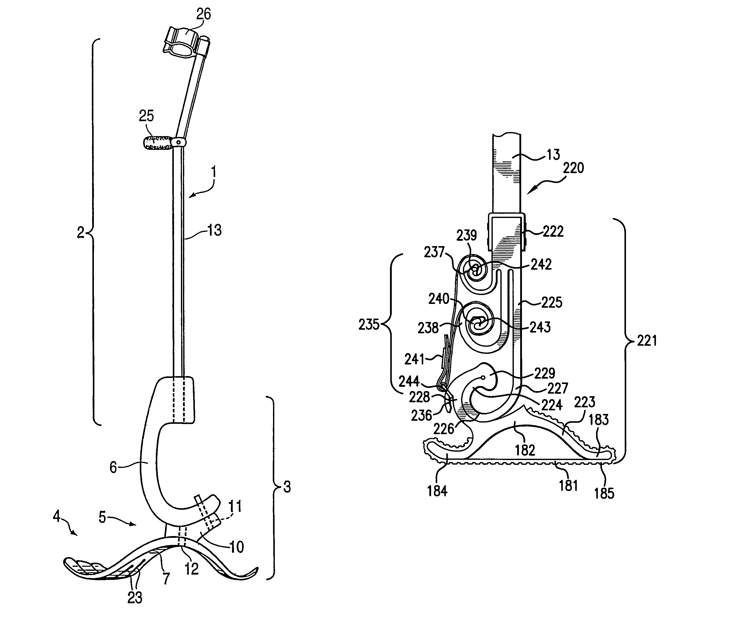
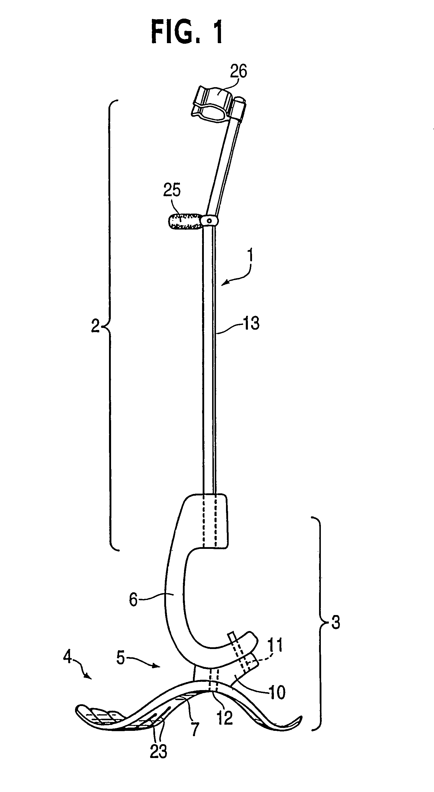
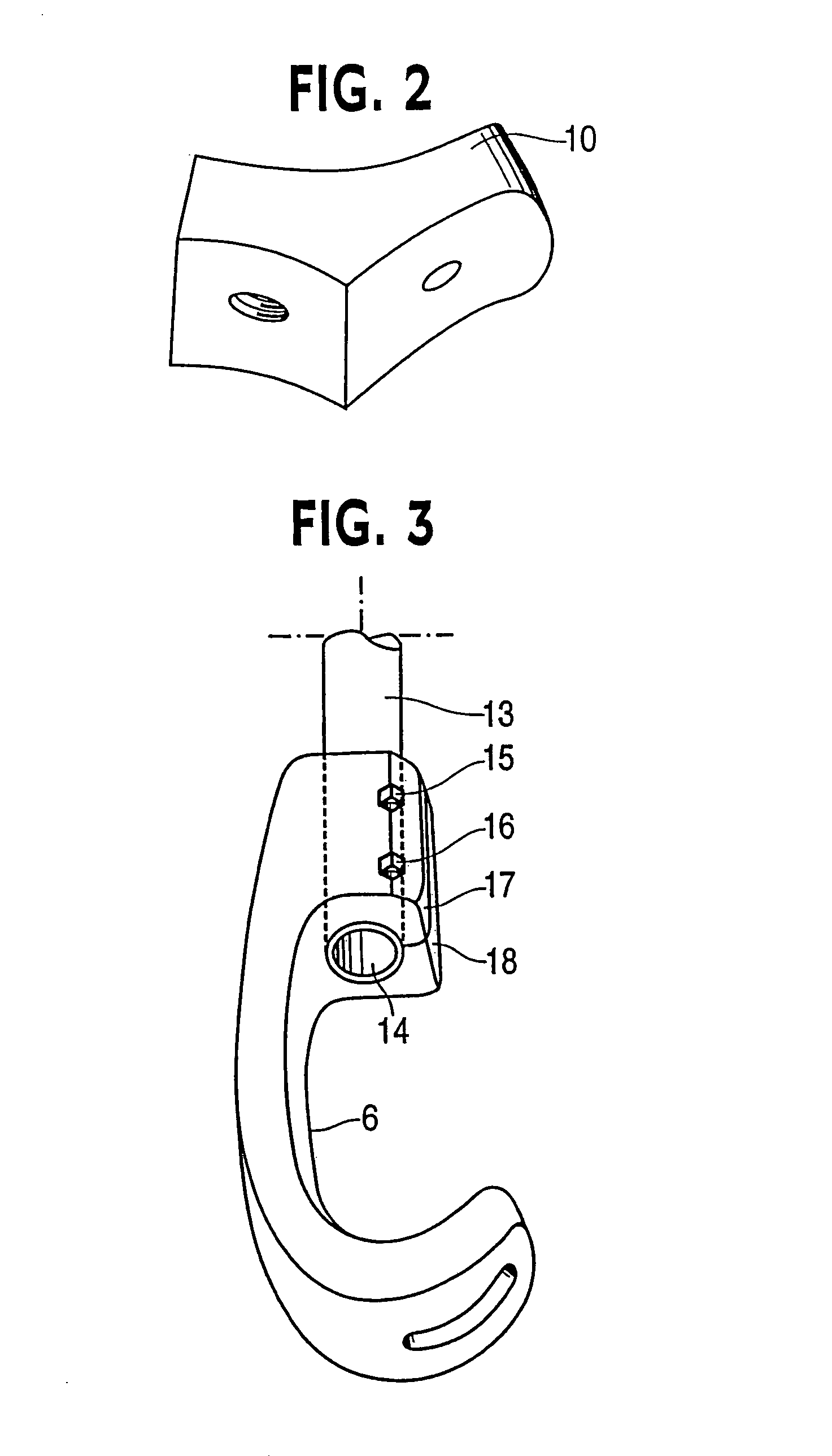
[0047]Referring now to FIGS. 1-3 of the drawings, a mobility assistance apparatus 1 according to a first embodiment is formed of a walking aid 2 in the form of a forearm crutch and a device 3 connected to a lower portion of the walking aid for ground engagement. The device 3 has a dynamic response characteristic to forces associated with ambulating using the walking aid which generates forward propulsion to aid mobility. The device 3 in the embodiment is a resilient lower extremity prosthesis, e.g. a prosthetic foot, which stores energy during force loading and releases stored energy during force unloading to generate propulsive force. In the example embodiment the device 3 is a prosthesis according to commonly owned U.S. Pat. No. 6,562,075.
[0048]The prosthesis 3 includes a resilient foot 4, ankle 5 and calf shank 6. The foot 4 includes a foot keel 7 and optionally a protective covering not shown in FIG. 1 but like covering 8 shown in outline in FIG. 4, for example. The covering 8, ...
PUM
Abstract
An improved mobility assistance apparatus for use by a person as a walking aid, e.g. a cane, crutch, or walker, has a support capable of bearing vertical forces during use of the apparatus as a walking aid and a resilient device connected to a lower portion of the support for ground engagement. The device has a dynamic response characteristic to forces associated with ambulating using the apparatus as a walking aid which generates propulsive force to aid mobility. Two coiled springs are monolithically formed with the device at an upper end thereof. A flexible elongated member is connected to a radially inner, free end of each of the coiled springs and extends about a return at a lower portion of the device for resiliently expanding the coiled springs to store energy with force loading of the apparatus during use and to release stored energy during force unloading to generate propulsive force to aid mobility. The dorsiflexion moment of the resilient device is an order of magnitude greater than a plantarflexion moment thereof to mimic human ankle joint function.
Description
RELATED APPLICATIONS[0001]This application is a continuation in part of application Ser. No. 11 / 411,133, filed Apr. 26, 2006, and now abandoned, which in turn is a continuation in part of application Ser. No. 10 / 915,724 filed Aug. 11, 2004, now U.S. Pat. No. 7,735,501 issued Jun. 15, 2010, which is a continuation in part of application Ser. Nos. 10 / 814,260 and 10 / 814,155 each filed Apr. 1, 2004, now respectively U.S. Pat. No. 7,611,543 issued Nov. 3, 2009, and U.S. Pat. No. 7,410,503 issued Aug. 12, 2008, which in turn are continuation in part applications of Ser. No. 10 / 263,795 filed Oct. 4, 2002, now U.S. Pat. No. 7,226,485 issued Jun. 5, 2007, which is a continuation of application Ser. No. 09 / 820,895 filed Mar. 30, 2001, now U.S. Pat. No. 6,562,075 issued May 13, 2003.[0002]This application is a continuation in part of application Ser. No. 10 / 473,682 file Sep. 30, 2003, now U.S. Pat. No. 7,507,259 issued Mar. 24, 2009, which is a U.S. national phase application under §371 of Int...
Claims
Application Information
Patent Timeline
Application Date:The date an application was filed.
Publication Date:The date a patent or application was officially published.
First Publication Date:The earliest publication date of a patent with the same application number.
Issue Date:Publication date of the patent grant document.
PCT Entry Date:The Entry date of PCT National Phase.
Estimated Expiry Date:The statutory expiry date of a patent right according to the Patent Law, and it is the longest term of protection that the patent right can achieve without the termination of the patent right due to other reasons(Term extension factor has been taken into account ).
Invalid Date:Actual expiry date is based on effective date or publication date of legal transaction data of invalid patent.