Image forming apparatus for marginless printing
a technology of image forming apparatus and marginless printing, which is applied in the direction of electrographic process apparatus, instruments, optics, etc., to achieve the effect of improving the precision of the image formation position
- Summary
- Abstract
- Description
- Claims
- Application Information
AI Technical Summary
Benefits of technology
Problems solved by technology
Method used
Image
Examples
first embodiment
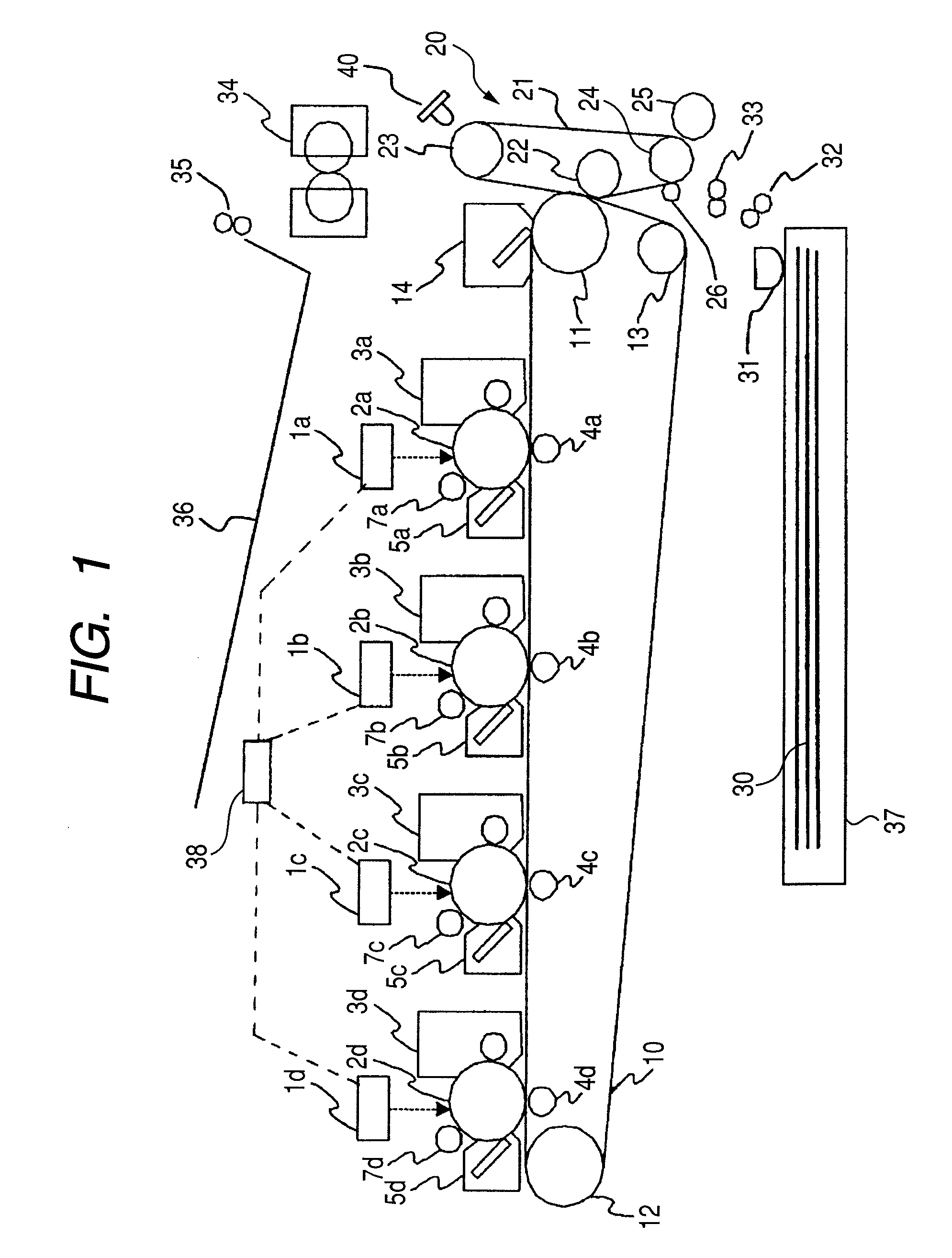
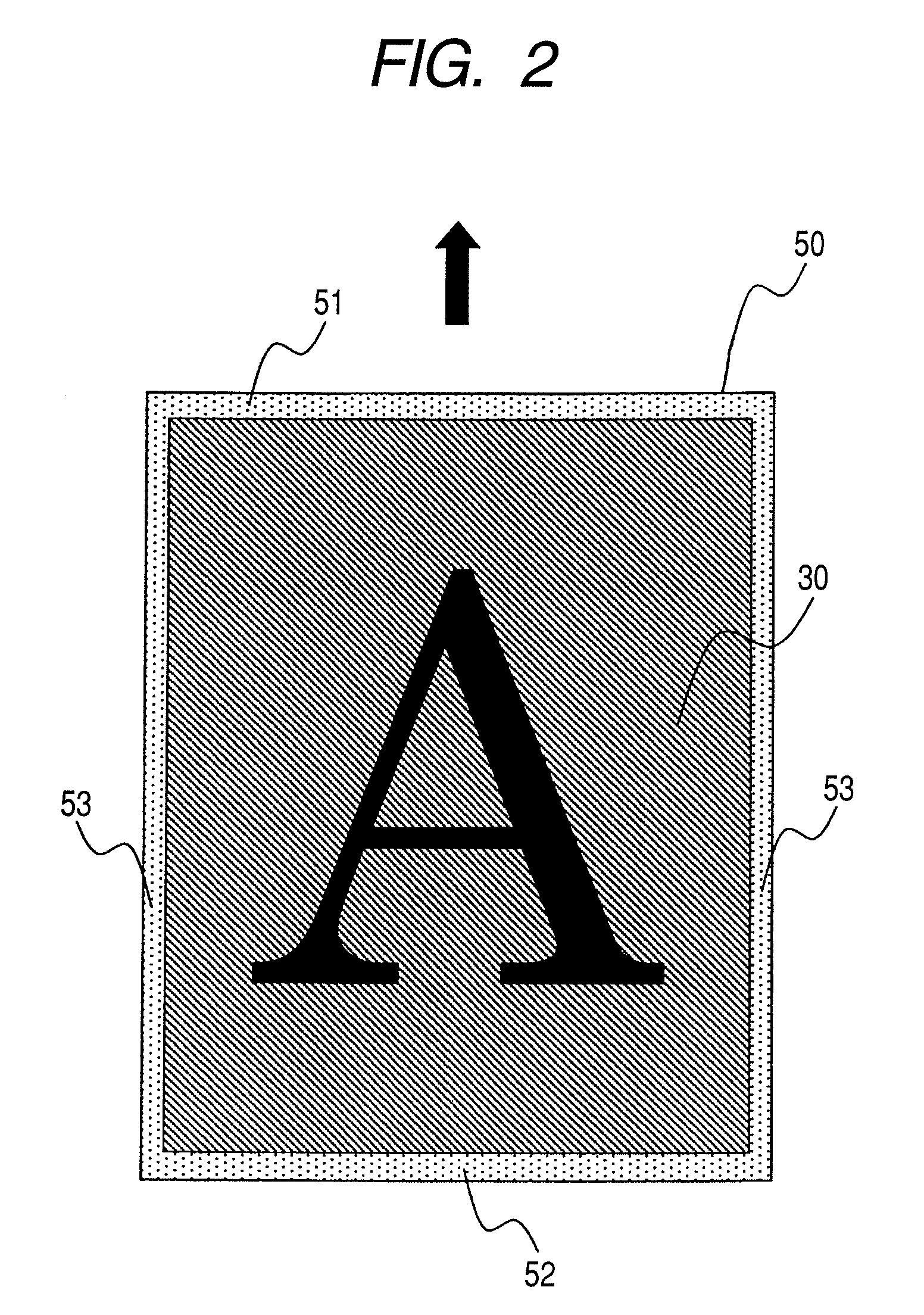
[0018]An image forming apparatus according to a first embodiment of the present invention is described with reference to FIGS. 1, 2, 3, 4 and 5. FIG. 1 is a schematic sectional view illustrating the schematic structure of the image forming apparatus. FIG. 2 is a top view illustrating the relation between the size of a recording material and the size of a toner image in marginless recording. FIG. 3 is a top view illustrating marginless recording on a recording material of the maximum size that is supported by the image forming apparatus. FIG. 4 is a top view illustrating marginless recording on a recording material of the minimum size that is supported by the image forming apparatus. FIG. 5 is a flowchart for describing processing of adjusting the image formation position with respect to a recording material in marginless recording. An image forming apparatus according to a first embodiment of the present invention is described with reference to FIGS. 1, 2, 3, 4 and 5. FIG. 1 is a sc...
second embodiment
[0049]An image forming apparatus according to a second embodiment of the present invention is described with reference to FIG. 6. The overall schematic structure of this image forming apparatus is the same as in the above-mentioned embodiment, and the description is not repeated here. Also, functions and structures of the second embodiment that are equivalent to those of the first embodiment are denoted by the same reference symbols to avoid repetitive description.
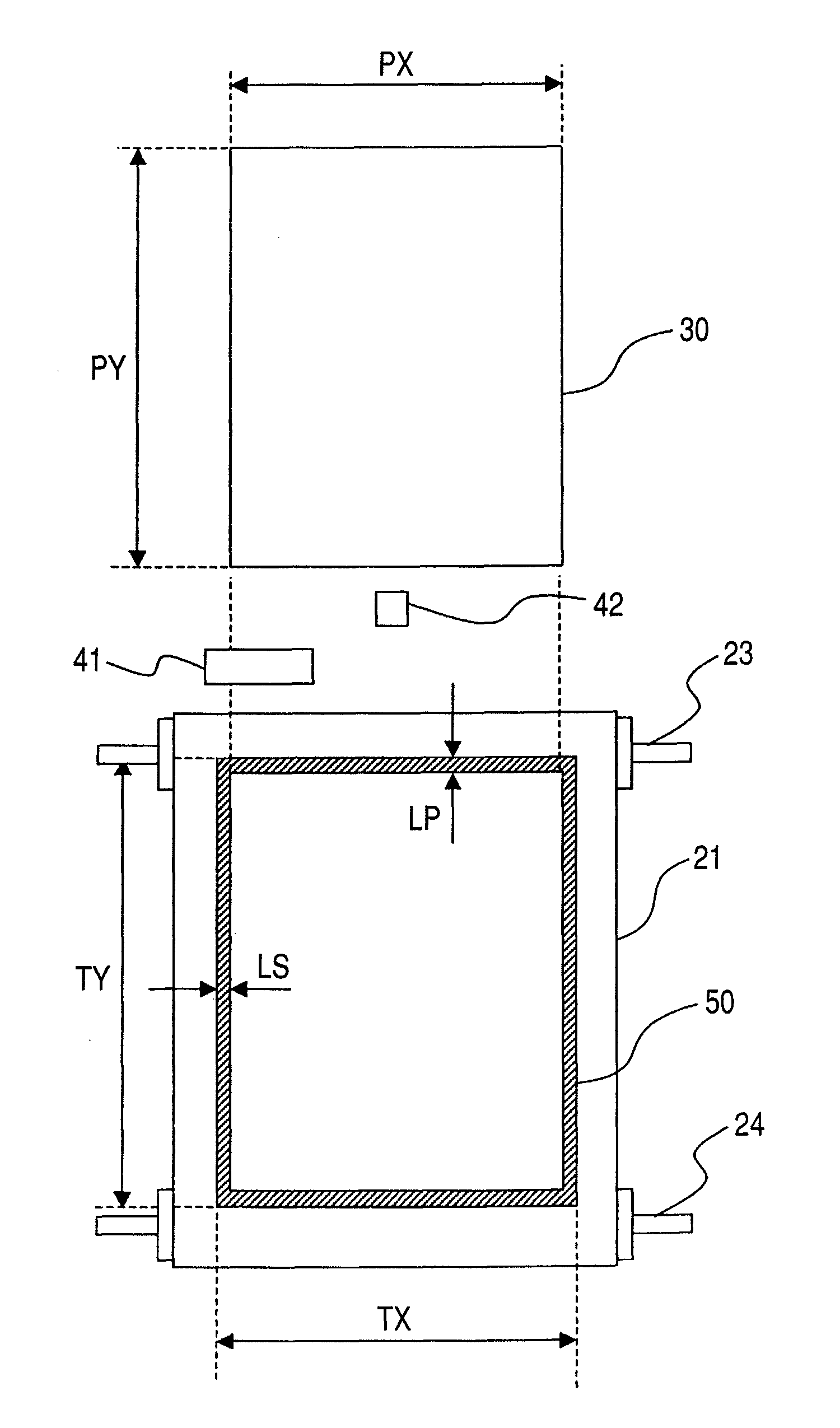
[0050]Described first is a detecting device for detecting toner images that are transferred to the secondary transfer belt 21 as a result of extending beyond the recording material 30.
[0051]As illustrated in FIG. 6, the secondary transfer section 20 is provided with a first detection sensor 41 and a second detection sensor 42, which are opposed to the secondary transfer drive roller 23 with the secondary transfer belt 21 interposed therebetween. The first detection sensor 41 and the second detection sensor 42 are detecting...
third embodiment
[0059]With reference to FIG. 7, an image forming apparatus according to a third embodiment of the present invention is described. In the third embodiment, the structure of a detecting device that detects an excess width of a toner image on an endless belt and the operation of adjusting the image formation position in marginless recording with the use of this detecting device are the same as in the above-mentioned embodiments, and the description thereof is not repeated here. Also, functions and structures of the third embodiment that are equivalent to those of the above-mentioned embodiments are denoted by the same reference symbols to avoid repetitive description.
[0060]The image forming apparatus given here as an example employs a method in which toner images of four colors formed on the respective photosensitive drums 2 are transferred directly to the recording material 30 that is attracted to and conveyed on a transfer / conveyor belt 70 as illustrated in FIG. 7. The transfer / conve...
PUM
 Abstract
Description
Claims
Application Information
 - R&D
- Intellectual Property
- Life Sciences
- Materials
- Tech Scout
- Unparalleled Data Quality
- Higher Quality Content
- 60% Fewer Hallucinations
Browse by: Latest US Patents, China's latest patents, Technical Efficacy Thesaurus, Application Domain, Technology Topic, Popular Technical Reports.
© 2025 PatSnap. All rights reserved.Legal|Privacy policy|Modern Slavery Act Transparency Statement|Sitemap|About US| Contact US: help@patsnap.com


