Binding strap used in connection with SpO2 sensor

a technology of spo2 sensor and binding strap, which is applied in the field of medical use, can solve the problems of loose binding strap, liable loss of binding strap, etc., and achieve the effect of hard to be los

Active Publication Date: 2011-06-07
SHENZHEN MINDRAY BIO MEDICAL ELECTRONICS CO LTD
View PDF8 Cites 0 Cited by
  • Summary
  • Abstract
  • Description
  • Claims
  • Application Information

AI Technical Summary

Benefits of technology

[0003]Therefore, an object of the present invention is to provide a binding strap used in connection with a SpO2 sensor, which could reliably secure the light emitting portion and the light receiving portion of the SpO2 sensor and is also hard to be lost when not in use.
[0019]The binding strap of the present invention is advantageous in that the light emitting portion and the light receiving portion of the SpO2 sensor might be tightly secured to the binding strap, and in that suitably designed first and second access openings ensure a coupling between the light emitting portion and the light receiving portion and the binding strap, thus even if the binding strap is separated with the light emitting portion and the light receiving portion, the binding strap is hard to be lost. Furthermore, since the end portion of the wrapping body could be inserted into the first inserting slot as well as the second slot (if necessary), the position of the light emitting portion and the light receiving portion will not be easily shifted.

Problems solved by technology

However, the conventional binding strap has a shortcoming in that the binding strap is liable to be lost due to carelessness of the user when the binding strap is temporarily not in use and meanwhile the light emitting portion and the light receiving portion are detached from respective mounting formations.
Unfortunately, the current mounting manner usually results in looseness of the binding strap.

Method used


Image

  • Binding strap used in connection with SpO2 sensor
  • Binding strap used in connection with SpO2 sensor
  • Binding strap used in connection with SpO2 sensor

Examples


Embodiment Construction

[0028]Hereinafter, the binding strap according to the present invention will be described with reference to the drawings.

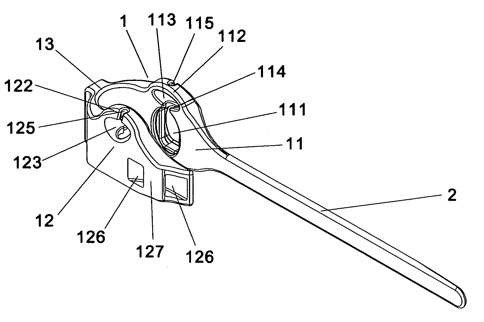
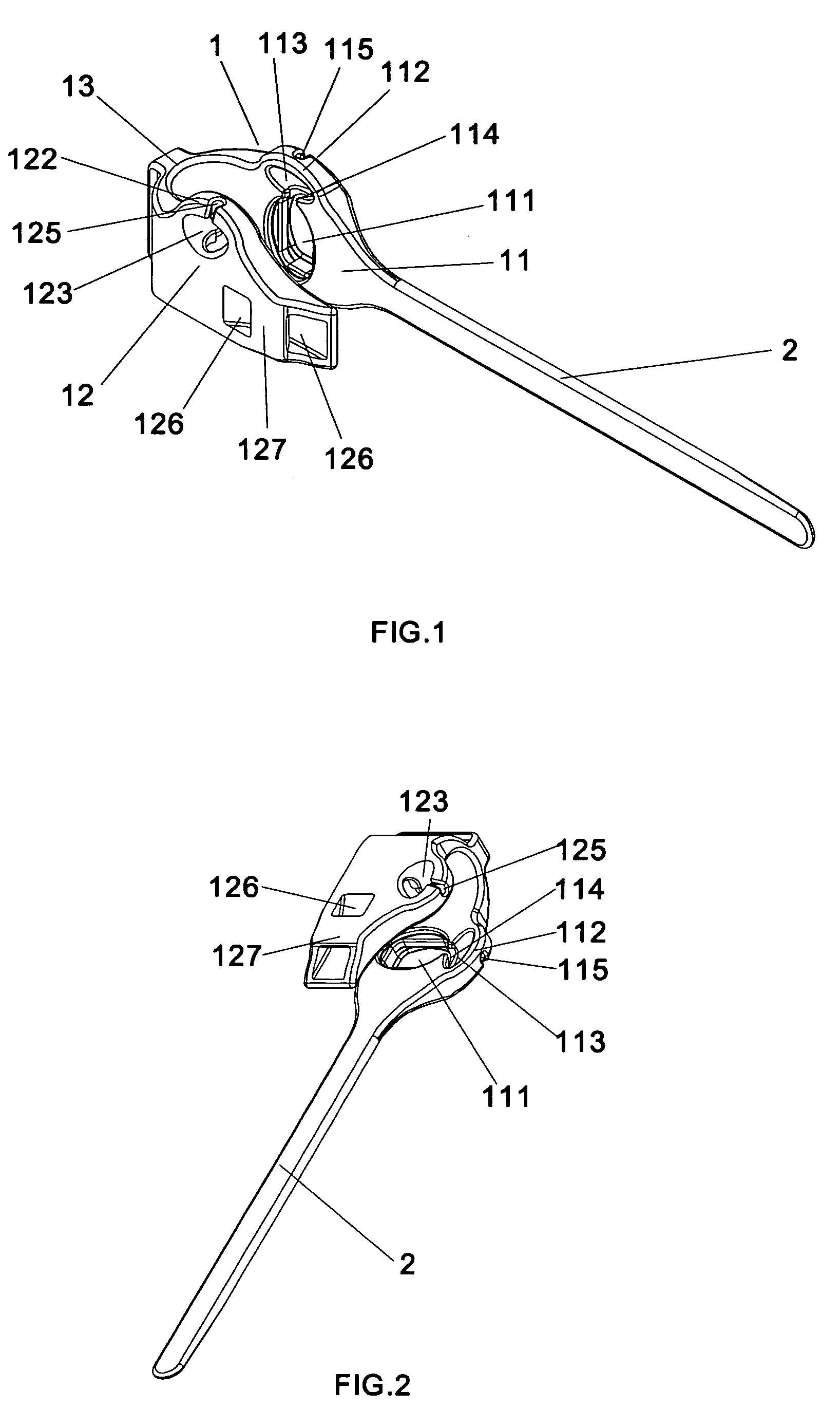
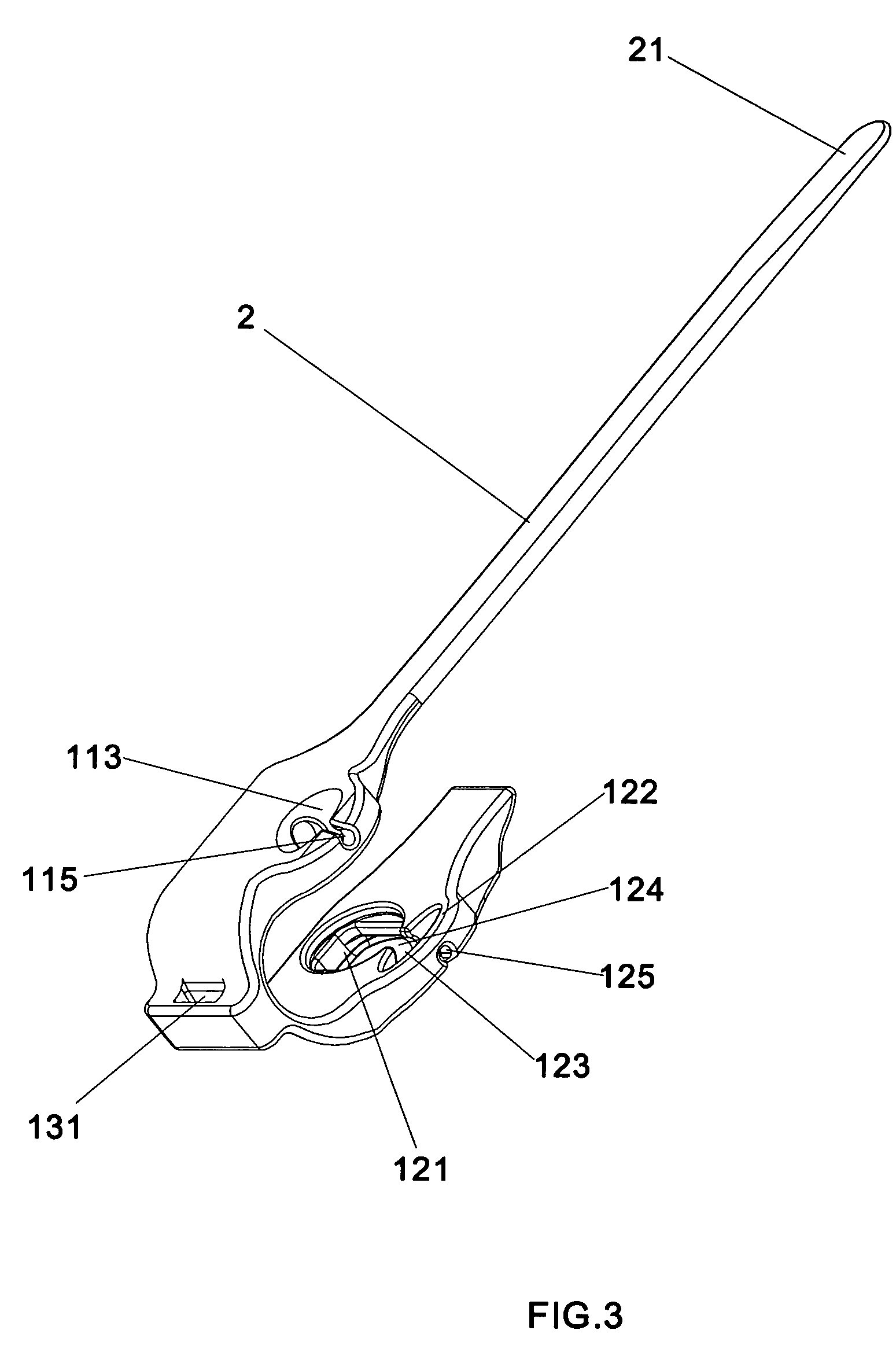
[0029]Referring now to FIGS. 1 to 5, the binding strap includes: a main body 1 in a substantially U-shape consisting of a first clamping portion 11, a second clamping portion 12, and an arc-shaped connection part 13 connecting the first clamping portion 11 and the second portions 12; and a wrapping body 2 in the shape of an elongated strip integrally extended from the first clamping portion 11. The binding strap may be made of elastically deformable materials such as silica gel. The SpO2 sensor includes a light emitting portion 3, a light receiving portion 4, and cables 5 connected with the light emitting portion and the light receiving portion. Generally, each of the light emitting portion and the light receiving portion has an elliptical shape. The binding strap of the present invention is designed to accommodate the light emitting portion and the light receivin...


PUM


Abstract

A binding strap used in connection with a SpO2 sensor comprises two clamping portions each of which is provided with an access opening for passing the light emitting portion or light receiving portion of the SpO2 sensor and a holding recess for holding corresponding light emitting portion or light receiving portion, wherein said access openings are designed to allow corresponding light emitting portion or light receiving portion to pass only when said access openings are undergoing a certain amount of deformation. The binding strap of the present invention is advantageous in that the light emitting portion and the light receiving portion of the SpO2 sensor might be tightly secured to the binding strap, and the lost of the binding strap when not use is ensured to be hard.

Description

FIELD OF THE INVENTION[0001]The present invention relates to a binding strap for medical use, in particular, to a binding strap used in connection with a SpO2 sensor.BACKGROUND OF THE INVENTION[0002]Generally, a SpO2 sensor is used to determine a saturation level of oxygen in blood, by means of a light emitting portion and a light receiving portion thereof which are to be fixed to a suitable position of a user, such as fingers, during the whole determination process. At this point, the SpO2 sensor is usually used in connection with an accessory which can hold the light emitting portion and the corresponding light receiving portion and also could secure said portions to the desired position. A binding strap may be the most commonly used form of the accessory, which may be provided with mounting formations capable of holding the light emitting portion and the light receiving portion of the SpO2 sensor therein, and which could be wound around the application position together with the ...

Claims


Application Information

Patent Timeline
Patent Type & Authority Patents(United States)
IPC IPC(8): A61B5/1455
CPCA61B5/14552A61B5/6838A61B5/6826
Inventor YANG, XINGBAOCAO, JIANFANGYE, JILUN
Owner SHENZHEN MINDRAY BIO MEDICAL ELECTRONICS CO LTD
Why Eureka
Try Eureka