Sabot

Inactive Publication Date: 2011-06-14
UNITED STATES OF AMERICA THE AS REPRESENTED BY THE SEC OF THE ARMY
View PDF15 Cites 7 Cited by
  • Summary
  • Abstract
  • Description
  • Claims
  • Application Information

AI Technical Summary

Benefits of technology

[0009]In view of the foregoing, an embodiment provides a two-piece sabot comprising a first piece comprising a first set of raised teeth configured on a first side of the first piece; and a second piece comprising a second set of raised teeth configured on a first side of the second piece, wherein the first set of raised teeth is dimensioned and configured to interlock with the second set of raised teeth. The sabot may further comprise a groove configured in the first and second set of raised teeth. Preferably, each of the first and second pieces comprise at least one indented conical end. Also, the first set of raised teeth is preferably spaced

Problems solved by technology

Accordingly, without adequate support from a sabot, a projectile may break up into many pieces when fired.
While several types of sabot designs are available, these designs may be overly cumbersome and may have high manufacturing costs associated with them.
Furthermore, when conventional smooth sabots (i.e., sabots with smooth surfaces and without means for holding the sabot pieces together) are used, they tend to slide back and forth in the gun barrel, which makes it difficult to line up the projectile and can create significant and unwanted pitch and yaw of the projectile.
Typically, the pusher is constructed of steel and also impacts the target, which in target practice is undesirable.
Furthermore, the pusher may interfere with the preferred trajectory of the projectile.

Method used


Image

  • Sabot
  • Sabot
  • Sabot

Examples


first embodiment

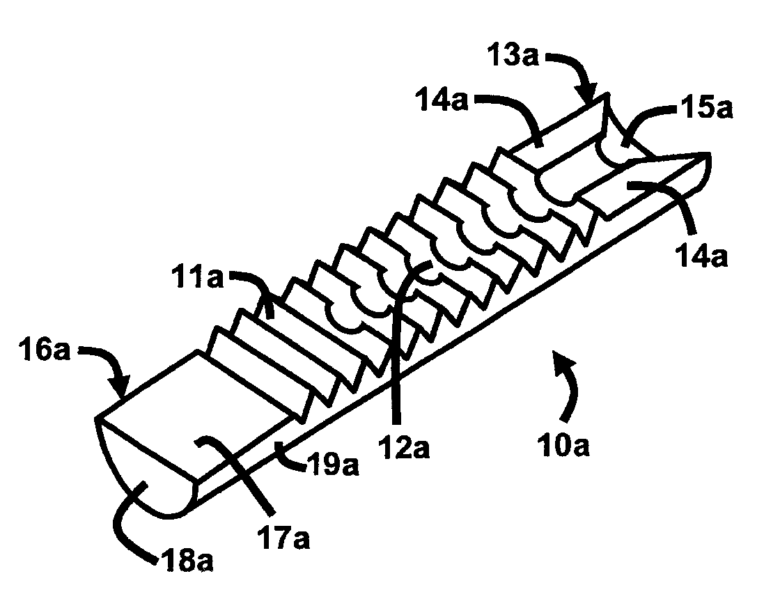
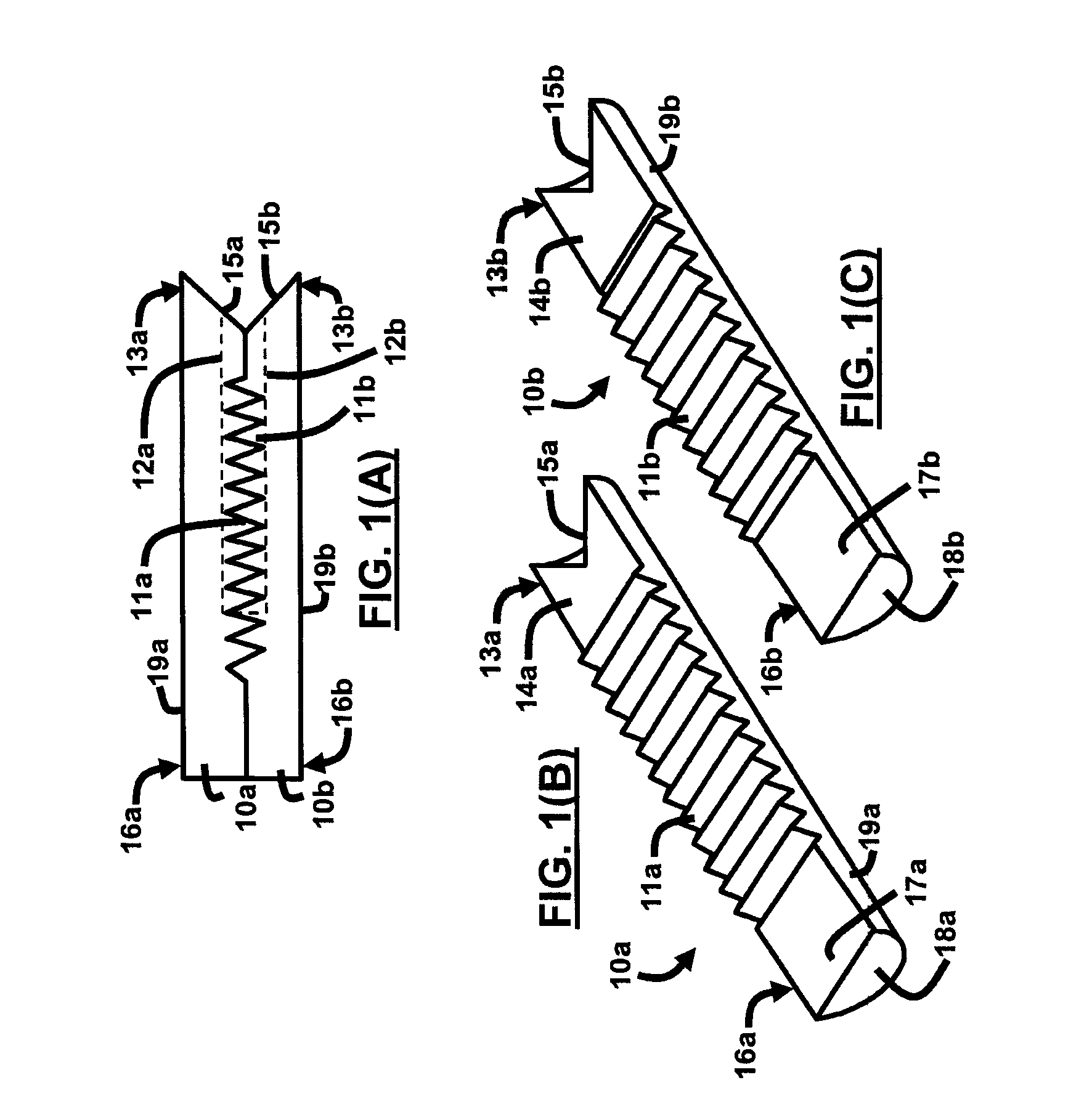
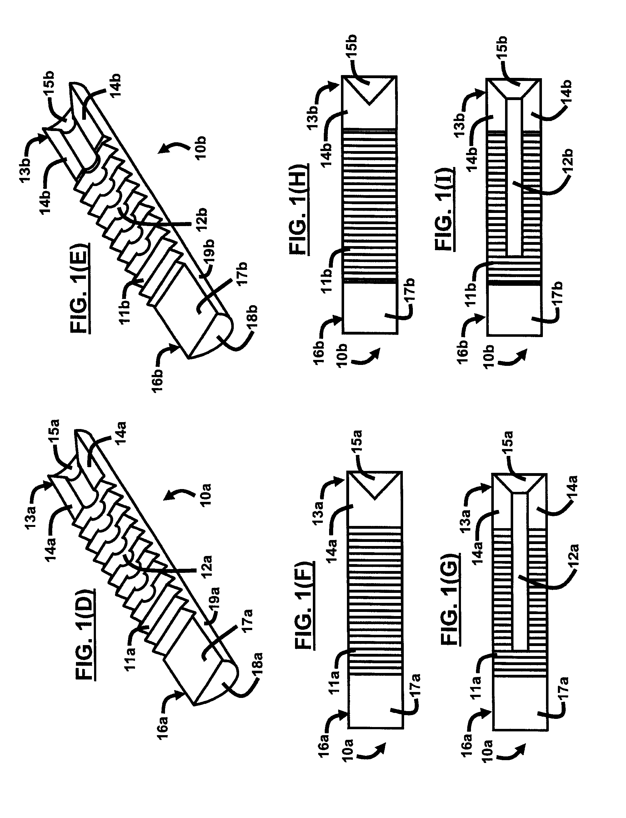
[0032]FIGS. 1(B) and 1(C) each illustrate complimentary halves of the sabot 10 (of FIG. 1(A)) herein. FIGS. 1(F) and 1(H) illustrate the top views of FIGS. 1(B) and 1(C), respectively. Each complementary sabot half 10a, 10b is generally configured as an elongated half-cylindrical structure comprising a first end 13a, 13b opposite a second end 16a, 16b and having a substantially curved surface 19a, 19b. Oppositely positioned from the curved surface 19a, 19b is a series of teeth 11a, 11b extending outwardly from the open-faced sabot halves 10a, 10b such that the teeth 11a of sabot half 10a mate with the teeth 11b of sabot half 10b. This mating of the teeth 11a, 11b is best illustrated in FIG. 1(A).

[0033]Additionally, each sabot half 10a, 10b has a conical indentation 15a, 15b at a first end 13a, 13b and has a flat surface 18a, 18b on the second end 16a, 16b. Because the sabot halves 10a, 10b are semi-cylindrically configured, the flat surface 18a, 18b assumes a semi-circular shape. T...

second embodiment

[0034]FIGS. 2(B) and 2(C) each illustrate complimentary halves of the sabot 20 (of FIG. 2(A)) herein. FIGS. 2(F) and 2(H) illustrate the top views of FIGS. 2(B) and 2(C), respectively. Each complementary sabot half 20a, 20b is generally configured as an elongated half-cylindrical structure comprising a first end 23a, 23b opposite a second end 26a, 26b and having a substantially curved surface 29a, 29b. Oppositely positioned from the curved surface 29a, 29b is a series of teeth 21a, 21b extending outwardly from the open-faced sabot halves 20a, 20b such that the teeth 21a of sabot half 20a mate with the teeth 21b of sabot half 20b. This mating of the teeth 21a, 21b is best illustrated in FIG. 2(A).

[0035]Furthermore, each sabot half 20a, 20b provides a conical indentation 25a, 25b, 28a, 28b at both the first ends 23a, 23b and second ends 26a, 26b, respectively. The conical indentation 25a is separated from the teeth 21a by a top portion 24a that is substantially flat to flush mate wit...


PUM


Abstract

A sabot with exactly two complimentary halves, wherein each half portion comprises teeth configured to interlock with teeth of the other half portion. The sabot may further comprise a semi-circular groove configured in the teeth of each half portion. Also, each half portion may comprise at least one indented conical end. Preferably, on each half portion, the teeth are spaced apart from the at least one indented conical end. Moreover, each half portion may comprise translucent polycarbonate material. Furthermore, each half portion may be adapted to flush mount together to form a substantially cylindrical configuration when the teeth are interlocked. Additionally, the sabot may further comprise a semi-circular groove configured in the teeth of each half portion, wherein the semi-circular groove extends to the at least one indented conical end.

Description

CROSS REFERENCE TO RELATED APPLICATION[0001]This application claims the benefit of U.S. Provisional Patent Application No. 60 / 857,494 filed on Nov. 8, 2006, the complete disclosure of which in its entirety is herein incorporated by reference.GOVERNMENT INTEREST[0002]The embodiments described herein may be manufactured, used, and / or licensed by or for the United States Government without the payment of royalties thereon.BACKGROUND[0003]1. Technical Field[0004]The embodiments herein generally relate to ammunition and explosives, and, more particularly, to sabots used when firing ammunition and explosives.[0005]2. Description of the Related Art[0006]In military ordnance arts, carriers for projectiles, known as sabots, have been used to facilitate the firing of a variety of ammunitions. Generally, a sabot is a carrier for a projectile that permits the firing of a variety of projectiles of a smaller caliber within a larger caliber weapon. Moreover, a sabot is used to provide structured s...

Claims


Application Information

Patent Timeline
IPC IPC(8): F42B14/06
CPCF42B14/067F42B14/064
Inventor KANE, RICKY G.WARD, MARK T
Owner UNITED STATES OF AMERICA THE AS REPRESENTED BY THE SEC OF THE ARMY
Why Eureka
Try Eureka