Ophthalmological device and ophthalmological measuring method

a technology of ophthalmological devices and measuring methods, applied in the field of opthalmological devices and opthalmological measuring methods, can solve problems such as measurement artifacts and insufficient detection of rotations of spherical corneas

Active Publication Date: 2011-06-14
SIS SURGICAL INSTR SYST
View PDF5 Cites 30 Cited by
  • Summary
  • Abstract
  • Description
  • Claims
  • Application Information

AI Technical Summary

Benefits of technology

[0005]It is an object of the present invention to propose a new opthalmologic device and a new opthalmologic measuring method which do not have the drawbacks of the state of the art, and which in particular make possible a coherent examination of the entire eye, in particular determination of topography and measurement values for structures of the anterior chamber of the eye, for example the corneal topography and corneal thickness, taking into account relative movements of the eye with respect to the device and rotations of the eye.
[0009]Preferably, the reference and comparative sections are each extracted as an array having equal number of rows and columns. Computing the displacement between extracted reference and comparative sections make it possible to take into consideration relative movements of the eye with respect to the device, particularly rotational movements, while examining coherently the entire eye.

Problems solved by technology

Since the eyes can move relative to the examination device, examination of the entire eye as set forth in U.S. Pat. No. 5,404,884 can lead to inaccuracies, however, because these relative movements are not registered and taken into account.
With comprehensive examination of the eye based on the merging of a multiplicity of cross-sectional images, measurement artifacts can result as a consequence of the difficulty of mutual alignment of the individual cross-sectional images.
Although the opthalmological device and opthalmological measuring method according to EP 1430829 make possible a coherent examination of the entire eye, taking into consideration the relative movements of the eye with respect to the device, rotations of a spherical cornea are not detected properly in the special case where the cornea rotates around its center.

Method used


Image

  • Ophthalmological device and ophthalmological measuring method
  • Ophthalmological device and ophthalmological measuring method
  • Ophthalmological device and ophthalmological measuring method

Examples


Embodiment Construction

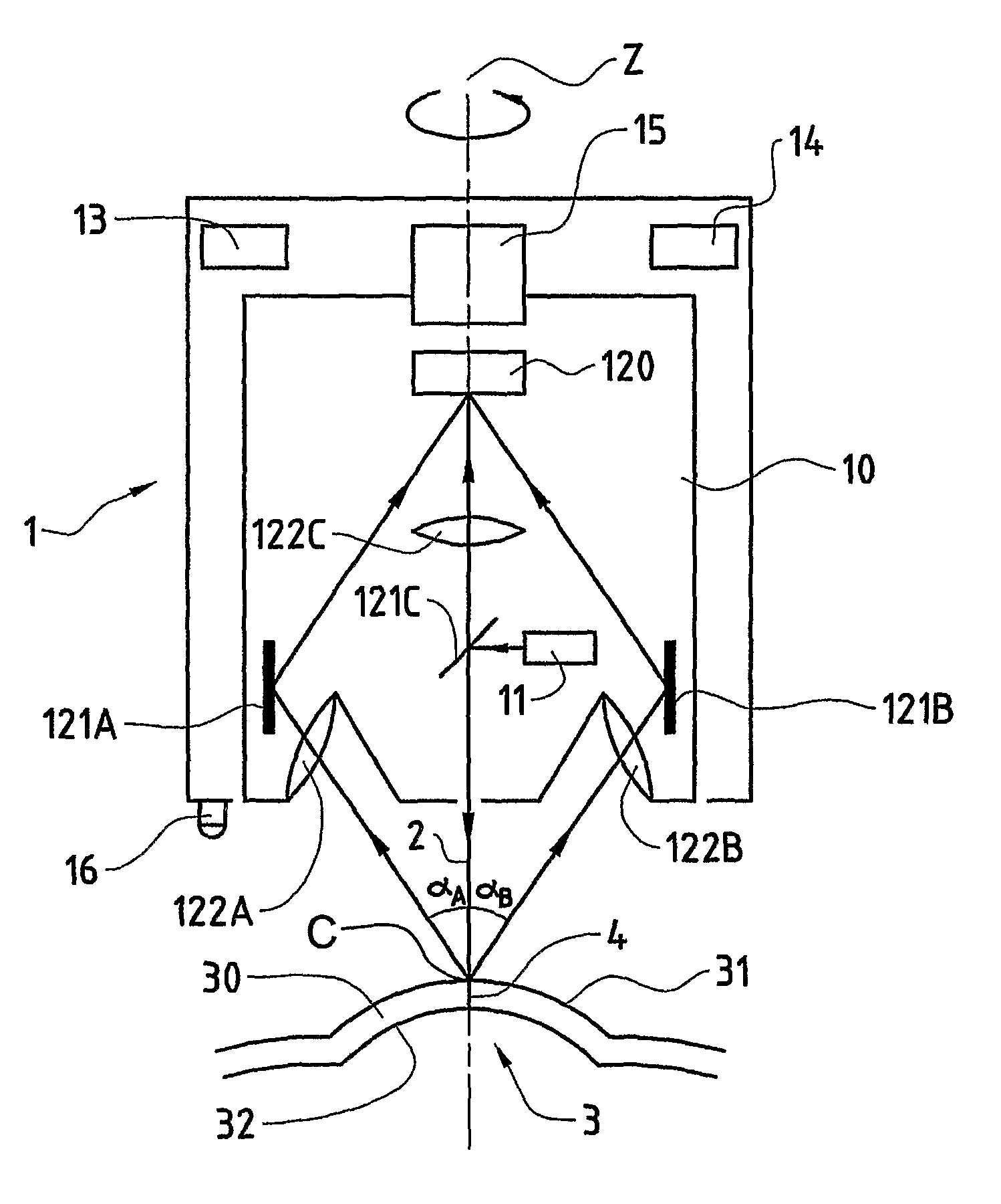
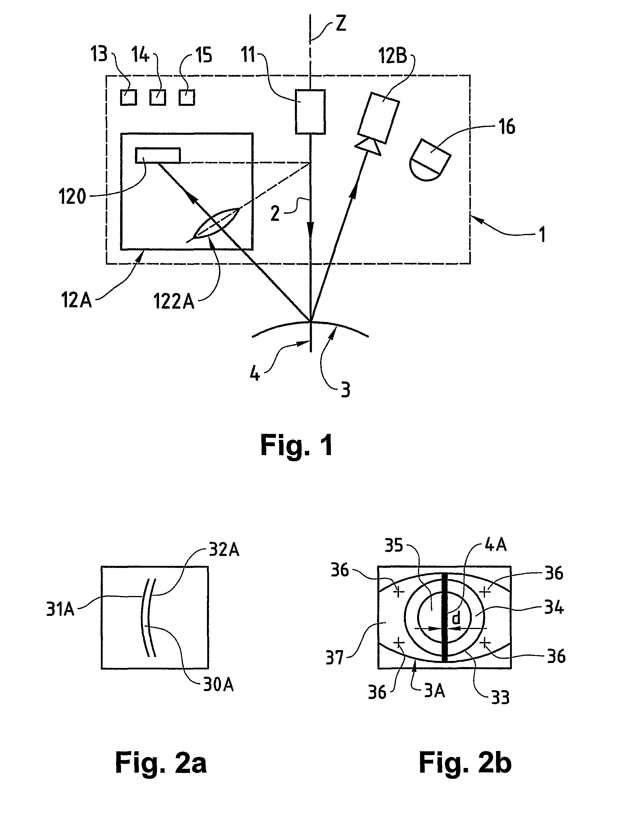
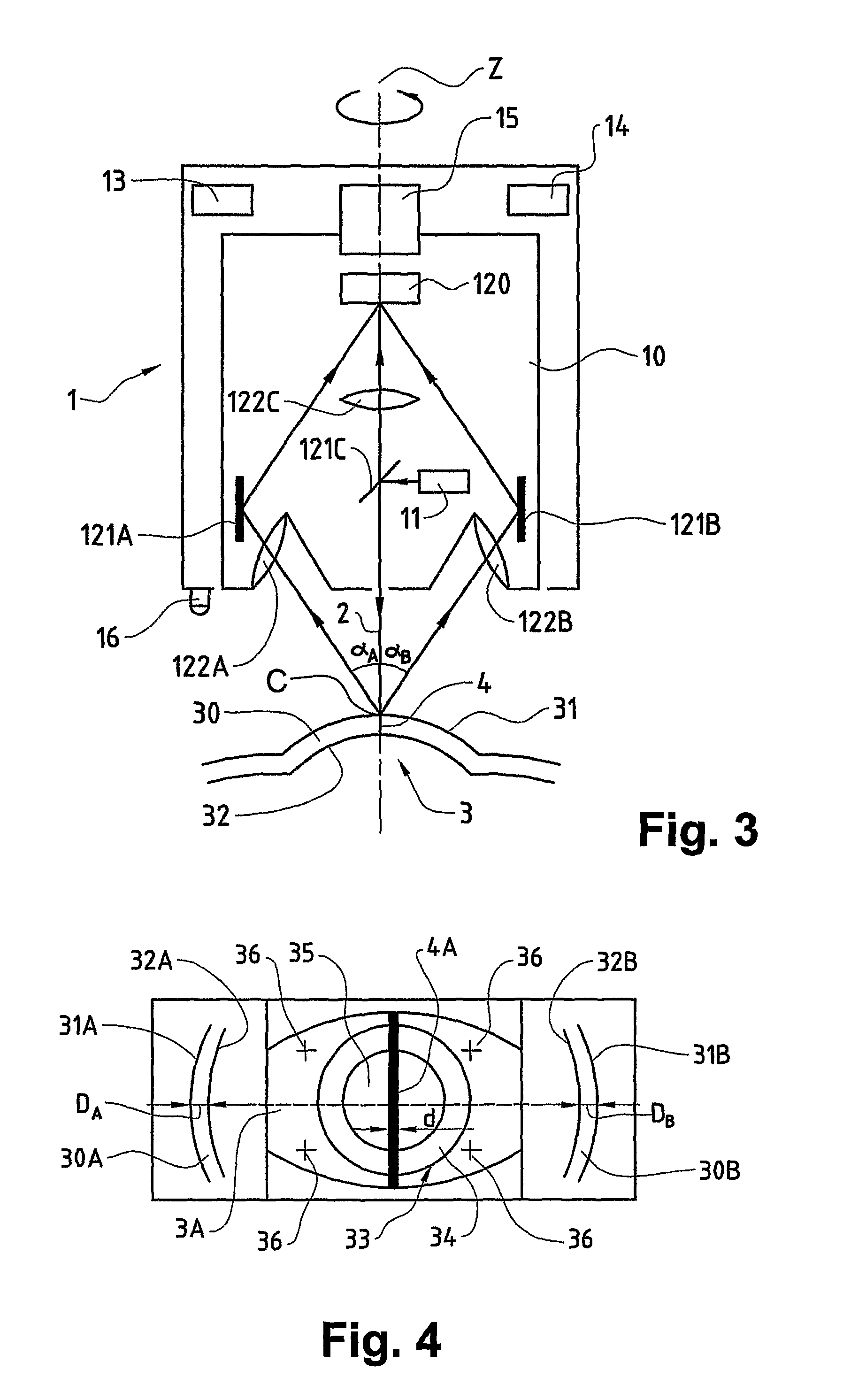
[0027]In FIGS. 1 and 3, reference numeral 1 refers to an opthalmological device, different embodiments of the opthalmologic device 1 being explained in the following description with reference to these figures. Otherwise same, corresponding components are designated in the figures by the same reference numerals.

[0028]As illustrated in FIGS. 1 and 3, the opthalmological device 1 comprises a light projector 11 for projection of a beam of rays 2 through a cross-sectional portion 4 of an eye 3, in particular through a cross-sectional portion of the cornea 30 of the eye 3. The beam of rays 2 is projected preferably in the form of a light slit. The light projector 11 comprises, for example, a slit lamp or a laser whose light is shaped into a fan through beam transformation optics.

[0029]Furthermore, the opthalmological device 1 comprises image-capturing means for capturing and storing a cross-sectional image 30A of at least one sub-area of the cross-sectional portion 4 illuminated by the l...


PUM


Abstract

An opthalmologic device and an opthalmologic measuring method in accordance with an embodiment of the present application in which, cross-sectional images of cross-sectional portions illuminated from different instrument positions by a light projector are captured in Scheimpflug configuration. Furthermore, corresponding top view images are also captured from the different instrument positions. At least one reference section and at least one comparative section are extracted from an initial instrument position or from an advanced instrument position, respectively. The displacement between the reference section and the comparative section is determined and the cross-sectional images are positioned relative to one another, based on the displacement. A coherent examination of the entire eye is made possible in which the relative movements of the eye with respect to the device, particularly rotational movements, are taken into consideration.

Description

CROSS REFERENCE TO RELATED APPLICATIONS[0001]The present application is a 35 U.S.C. §§371 national phase conversion of PCT / CH2006 / 000153, filed Mar. 16, 2006. The PCT International Application was published in the English language.FIELD OF THE INVENTION[0002]The present invention relates to an opthalmological device and an opthalmological measuring method. Specifically, the present invention relates to an opthalmological device and an opthalmological measuring method having a light projector projecting a beam of rays through a cross-sectional portion of an eye, image-capturing means disposed in Scheimpflug configuration with respect to the beam of rays and capturing in a first instrument position a cross-sectional image of at least a sub-area of the cross-sectional portion, and a motion driver moving the first image-capturing means to a second instrument position, at which second instrument position the first image-capturing means are disposed in Scheimpflug configuration with respe...

Claims


Application Information

Patent Timeline
Patent Type & Authority Patents(United States)
IPC IPC(8): A61B3/14A61B3/10
CPCA61B3/152A61B3/113
Inventor CATTIN-LIEBL, ROGER
Owner SIS SURGICAL INSTR SYST
Why Eureka
Try Eureka