Formliner and method of use

a technology of formliners and concrete, applied in the field of concrete formliners, can solve the problems of easy to notice unsightly seams, create significant visible seams between the formliners, and compromise the appearance of the exposed surface of the concr

Active Publication Date: 2011-06-21
PRIME FORMING & CONSTR SUPPLIES INC DBA FITZGERALD FORMLINERS +1
View PDF21 Cites 22 Cited by
  • Summary
  • Abstract
  • Description
  • Claims
  • Application Information

AI Technical Summary

Benefits of technology

[0010]As noted above, in recent years, significant advances have been made in the art of concrete laying. Various techniques and equipment have been developed that allow for the creation of decorative patterns in the concrete, especially a faux stone or brick appearance. The results of such techniques and equipment provide the appearance of stone or brick without the cost.
[0012]Accordingly, in at least one embodiment disclosed herein, an improved formliner is provided which minimizes and / or eliminates the seams between multiple interconnected formliners. One of the advantages of embodiments disclosed herein is that a seam between adjacent formliners is created along corners at or along a bottom portion of a prepared formliner assembly or mold cavity of a casting. For example, in some embodiments, a seam between adjacent and / or interconnected formliners can be formed by an edge of a first formliner positioned against or in a corner or face of an adjacent second formliner. In some embodiments, the seam can lie along the intersection of one or more surfaces, such as at a corner of a mold or formwork. Additionally, in other embodiments, the seam can be positioned such that the weight of a curable material, such as concrete, against the formliners causes the formliners to be pressed against each other with greater force thereby minimizing and / or eliminating the seam between the adjacent formliners.
[0014]For example, a given interconnecting portion of the formliner can nest within another given interconnecting portion of the formliner. In such embodiments, as well as in other embodiments disclosed herein, the formliner can be configured such that upper surfaces of the interconnected formliners are flush with each other and joints between the interconnected formliners are minimized. Thus, embodiments disclosed herein can achieve a natural appearance of faux stone and brick with minimized, negligible, or imperceptible seaming.
[0021]It is contemplated that a first formliner can be interconnected with a second formliner by nesting the overlaying the first section of the rib of the first formliner onto the second section of the rib of the second formliner such that the second section of the rib of the second formliner is nested within the first section of the rib of the first formliner. Further, exterior surfaces of the ribs of the first formliner and the second formliner can be flush with each other upon nesting of the second section of the second formliner within the first section of the first formliner. Additionally, an opening in the first section of the first formliner can mate against a transition zone of the second formliner such that visible seams in the decorative pattern are minimized when the first formliner and the second formliner are interconnected in use.
[0036]Furthermore, some embodiments of the method can allow for minimized and / or eliminated seaming between the formliners. For example, the overlapping ridges of the first formliner can be configured to include edges that extend downwardly toward a bottom portion of respective shaped regions located adjacent to overlapped ridges of the second formliner. The method can comprise placing the curable material against the overlapping ridges of the first formliner such that the edges of the overlapping ridges of the first formliner are urged adjacent to the bottom portion of respective shaped regions to minimize and / or eliminate a seam formed between the edges and the bottom portion of the respective shaped regions.
[0037]In accordance with some embodiments, it is contemplated that the formliner can be attached to another formliner and / or to a form work by means of an adhesive. Such an adhesive can be applied to the formliner at the site. However, in some embodiments, the formliner can comprise an adhesive that can be activated or exposed in order to enable adhesive attachment of the formliner to another formliner or to a form work. For example, the adhesive can be pre-applied to the formliner, which adhesive can be exposed by removing a strip or by dampening with a liquid such as water or otherwise. In this manner, the formliner can be securely attached in a pattern and / or in a form work to facilitate handling and placement of the formliner.

Problems solved by technology

For example, in order to create a large pattern or casting with prior art formliners, the formliners are merely placed together using butt joints, thus creating significant visible seams between the formliners.
As a result, the appearance of the exposed surface of the concrete is compromised.
An unsightly seam is very easy to notice and takes a substantial amount of time and effort to remove from cured concrete.
Further, in large-scale projects, it is simply too cost prohibitive to re-work the cured concrete in order to remove the seams.
As such, the seams are simply left in place resulting in an inferior concrete product.

Method used


Image

  • Formliner and method of use
  • Formliner and method of use
  • Formliner and method of use

Examples


Embodiment Construction

[0056]While the present description sets forth specific details of various embodiments, it will be appreciated that the description is illustrative only and should not be construed in any way as limiting. Furthermore, various applications of such embodiments and modifications thereto, which may occur to those who are skilled in the art, are also encompassed by the general concepts described herein.

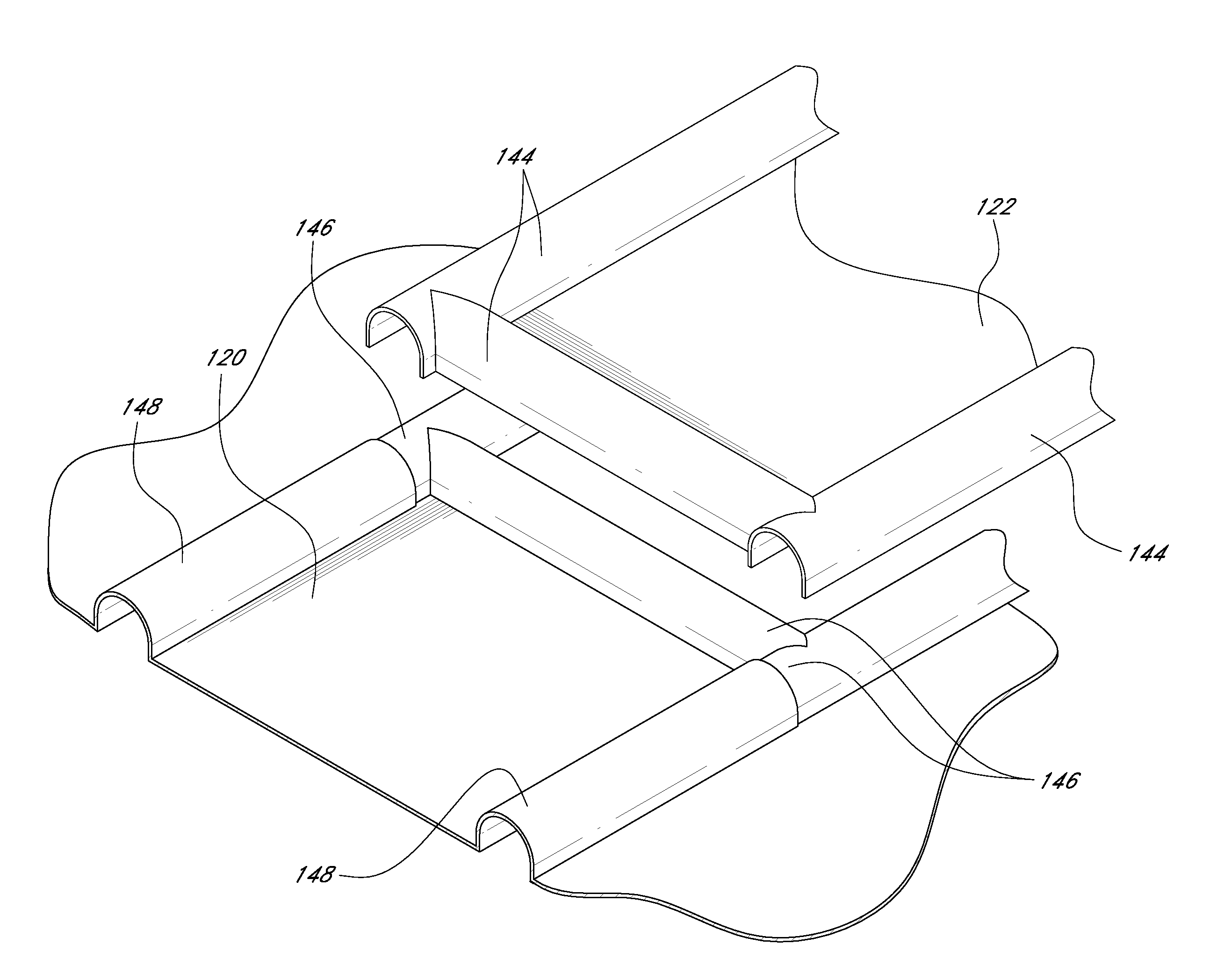
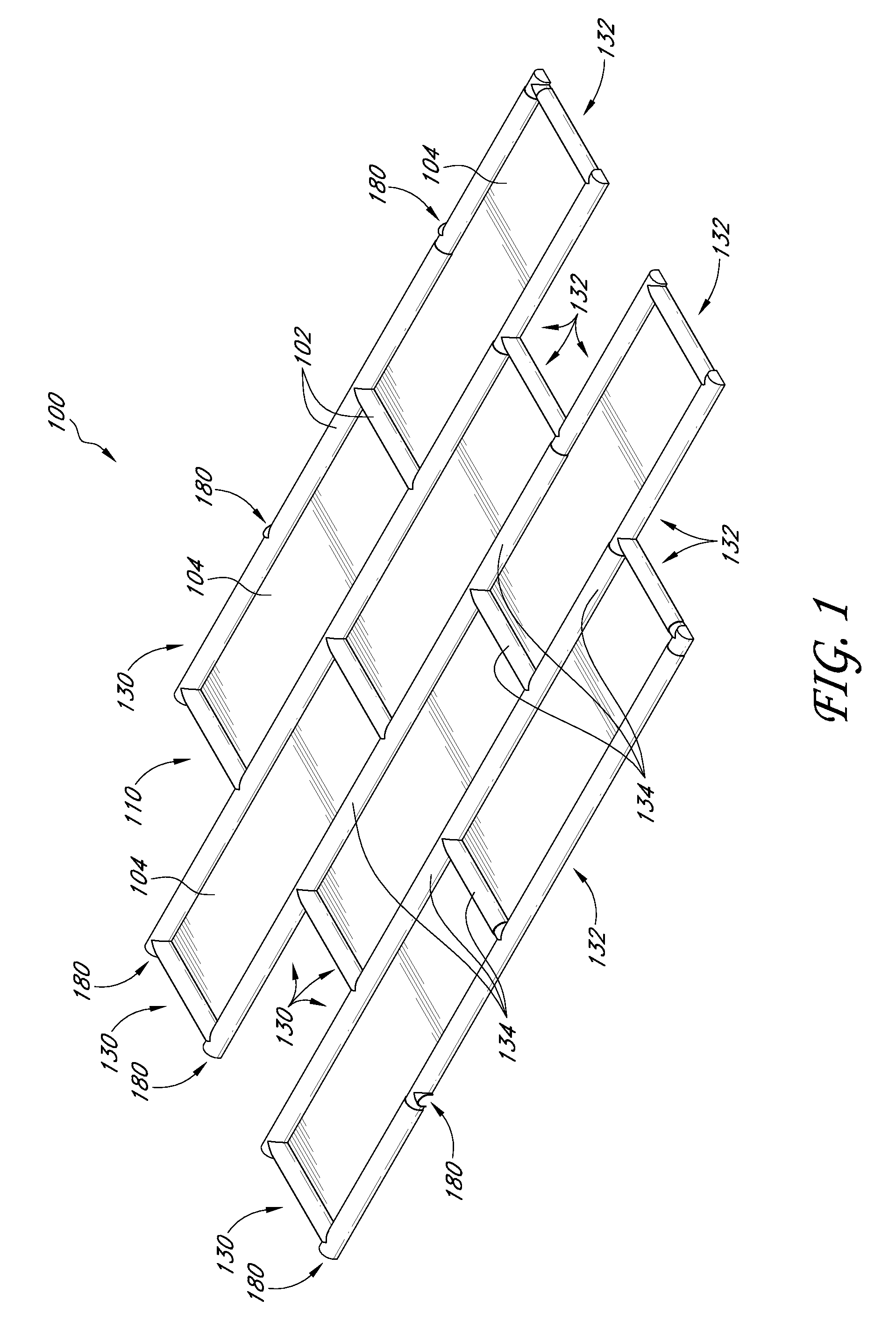
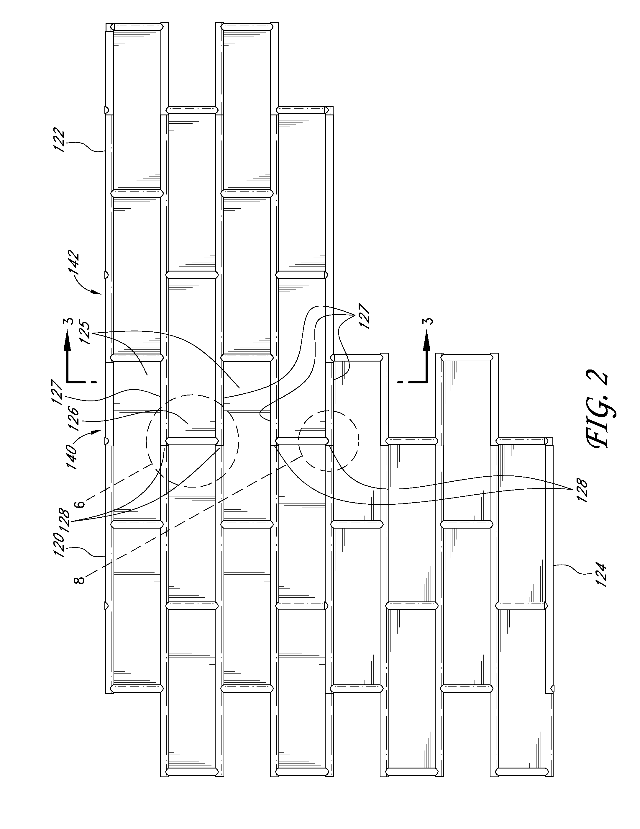
[0057]As generally discussed above, embodiments of the present inventions are advantageously configured in order to enhance the aesthetic finish of a concrete structure. In particular, embodiments disclosed herein can be used to create a natural, seamless appearance of brick, stone, and other types of materials in a concrete structure.

[0058]In contrast to prior art formliners that produce an inferior quality product, the structures of embodiments of the formliner disclosed herein, which can also be referred to as a panel or sheet, allow the formliner to create decorative patterns that are ...


PUM

PropertyMeasurementUnit
rectangular shapeaaaaaaaaaa
perimeteraaaaaaaaaa
timeaaaaaaaaaa

Abstract

A formliner and method of use are provided in order to minimize and / or eliminate visible seaming between interconnected formliners. In some embodiments, the formliner can comprise raised sections that define interrelated inner and outer dimensions. In this manner, a given portion of a first formliner can mate with another given portion of a second formliner in a nested manner. As such, edges of the interconnected formliners can be discreetly hidden along features of the formliner pattern to reduce and / or eliminate visible seaming between the formliners.

Description

BACKGROUND[0001]1. Field of the Inventions[0002]The present inventions relate generally to concrete formliners and methods of using the same. More specifically, the present inventions relate to an improved formliner that reduces and / or eliminates visible seams in order to create a more natural appearance in a finished product.[0003]2. Description of the Related Art[0004]Decorative masonry and concrete construction have become increasingly popular in recent years. The facades of homes and other buildings that had previously been constructed in very simple and plain concrete are now being replaced with either decorative stone and brick or decorative concrete construction.[0005]As a result of the increased demand for stone and brick work, various improvements have been made in stone and brick masonry and concrete construction. These improvements have lowered the cost for such construction by decreasing the time or skill requirements previously needed to perform such work.[0006]For exam...

Claims


Application Information

Patent Timeline
Patent Type & Authority Patents(United States)
IPC IPC(8): E04G11/36
CPCB28B7/0073E04F13/147E04G9/10E04F13/185E04F2201/091
Inventor FITZGERALD, EDWARD DANIELSHEEHAN, BRIAN EUGENE
Owner PRIME FORMING & CONSTR SUPPLIES INC DBA FITZGERALD FORMLINERS
Why Eureka
Try Eureka